Wednesday, July 23, 2025

Maintaining refrigerator cars

I have a very specific piece of maintenance for model refrigerator cars to mention today, namely ice hatch latches. These are very visible on a model, being located on the roof, so missing latches are quite evident, and of course should not be missing. But their location also means that they are quite vulnerable to being brushed or knocked off and lost in the weeds. So something like the view below, showing my model of PFE 64739, is not what we want. (You can click to enlarge if you wish.)

Replacement latches may be found in extra parts sprues from previous kit builds, though these are often rather too big, especially in thickness. A far better solution is the etched stainless steel latches from Plano Model Products, their part number 12079 in HO scale. The fret is shown below. Obviously there are six sets of four. These may not match the latches of every reefer owner, but they suit my PFE cars.

I pre-paint these, usually some variation of boxcar red, since most of my reefers have that color roof and ends. I usually cut them from the sprue with a hobby knife, then I apply these nice latches with canopy glue. Here they are attached to PFE 64739. This model is built from Sunshine parts, given to me by Frank Hodina, and assembled with the high hatch coamings sometimes seen on rebuilt cars.

These latches can also enhance models of somewhat lower detail level. Years ago I posted a description of the efforts I’ve made to upgrade Athearn steel reefer models, particularly removing the gross “hinges” on the ice hatches (see that post at: https://modelingthesp.blogspot.com/2012/08/ujpgrading-old-models-athearn-reefers.html ). 

The Athearn ice hatch latches are also considerably oversize, so replacing them with the Plano parts is a definite improvement. Note also below that I have replaced the kit running board with etched metal, replaced the Athearn brake wheel, and added wire grab irons, placard board, and fan shaft, along with decal re-lettering. 

I continue to need to replace latch bars that have been knocked off of reefer models in operating sessions, so I expect to keep on needing those Plano 12079 sets. Appearance of this detail part speaks for itself.

Tony Thompson 

Sunday, July 20, 2025

Nightime on the Santa Cruz Northern

 I have occasionally posted descriptions of operating sessions on Jim Providenza’s venerable Santa Cruz Northern (SCN) layout. I say “venerable” because its roots go back 40 years or more, and during most of that time, it has been demonstrating realistic operation to many a novice in that aspect of the hobby.

 There are two posts that I might cite as previous examples of operating commentary. The first (with oddly yellowish photos) dates back to 2013, and can be found here: https://modelingthesp.blogspot.com/2013/06/an-operating-session-at-jim-providenzas.html . Later I followed up with an extension post: https://modelingthesp.blogspot.com/2016/05/operating-on-scn.html

Given the information provided in these two posts, I won’t repeat details of the layout background, except to show the system map (also venerable), from San Jose at the top of the map, to Santa Cruz on the Pacific shore at the bottom. 

This was once the route of the South Pacific Coast narrow-gauge, later standard-gauged by the Southern Pacific, and in Jim’s concept, eventually sold to joint ownership by Western Pacific and Santa Fe and operated under the Santa Cruz Northern name (by now, in 1971, in receivership).

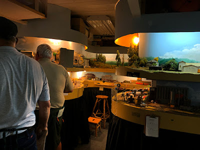
My point today is that even a venerable layout can occasionally try something new. This weekend Jim hosted an evening session, and as he was about to turn on the room lights, someone said, “Hey, we are in the night portion of the layout clock, why not leave the lights off?” The layout lights behind the fascia were on, just the general room lights were off. Here’s a view of the room.

Of course one’s pupils soon adjust to the lower light level, and it no longer seems very dark, but it was actually rather atmospheric. We could, however, look through the doorway into the kitchen, where sat the dispatcher, Brynn Ekroot, here caught studying the timetable (wouldn’t a dispatcher already know that stuff?). 

One thing  I enjoyed on this visit to the SCN was to see a particular boxcar, spotted at Fallon. Here’s my photo:

Why is this interesting? This is a car I gave to Jim some while back. I had upgraded the Athearn car with wire grab irons and A-Line sill steps, cut off the horrible door “claws,” and discarded the equally horrible Athearn brake wheel of the day.  I replaced the brake wheel with a nice Ajax wheel from Walthers, extended the width of the brake step, and added supports underneath (you can click on the photo to enlarge it).

So why hadn’t I kept the model? After doing that work, I discovered that this particular P&LE paint scheme postdated my 1953 modeling year, and I had offered to donate the car to a friend in Pittsburgh who was going to model the early 1970s, when running boards were being removed from house cars. So I pulled off the running board, but then his plans changed and I kept the car. But the car fits Jim’s 1971 era, so now it lives on the SCN. I was glad to see it alive and well.

Tony Thompson 

Thursday, July 17, 2025

Waybills, Part 121: Industry research for waybills

In creating waybills for layout operation, it is natural to have outbound and inbound loads to the industrial spurs on one’s layout but where do those loads go, and where do they come from? This is a long-standing challenge for model railroad operations, and beyond simply making up industry names, is worth considering. 

As I have often described, and now only briefly mention, railroad-issued “shipper guides” are a superb resource. In fact, I have written several blog posts about them, which can be reached by using the term “shipper guide” as the search term in the search box at upper right; or my more general post on the topic is here: https://modelingthesp.blogspot.com/2015/11/waybills-part-44-shipper-guides.html .

As an example of one of these volumes, below is shown a 1943 guide from the Milwaukee Road. You can obtain this and 22 others from Ted Schnepf’s Rails Unlimited site, described here: https://railsunlimited.ribbonrail.com/Books/shippers.html .  

This guide enabled me to identify a major producer of steel forgings, Ladish Drop Forge, in Cudahy, Wisconsin.  The waybill I made is for drop forgings sent to be finish machined at one of my layout industries, Santa Maria Tool & Machine. Note incidentally, that such a shipment could move under “milling in transit” rules, as I’ve explained previously (for example, this post: https://modelingthesp.blogspot.com/2016/08/wayblls-part-51-more-on-prototype-in.html ).

Another example of an inbound load that I recently created was also destined to that same machine shop on my layout. This business I imagined as doing custom machining and fabrication for manufacturers. Of course many inbound loads are castings or forgings to finish machine, as shown in the example above, but machine tools may also be delivered from time to time. For example, a vertical milling machine.

Anyone familiar with machine shops or machinists knows that the usual synonym for such a machine is a “Bridgeport.” That name comes from a prominent maker of such milling machines, the Bridgeport Machines Company of Bridgeport, Connecticut (see for example the Wikipedia entry, at: https://en.wikipedia.org/wiki/Bridgeport_(machine_tool_brand) ). The Wikipedia entry also gives numerous model designations for a more specific cargo name if you wish. Here’s a waybill.  

A final example is a shipment of cement from one of the several Portland cement plants in California, located on the Santa Fe in Victorville, California. One can easily search on the internet for cement plant locations anywhere in the U.S. Here the load is directed to my district facility for California Division of Highways (today known as CalTrans). 

All these examples are from readily available on-line resources. As my friend Kyle Wyatt used to say, for lots of research challenges, “Google is your friend,” and I certainly often act on that advice.

Tony Thompson 

Monday, July 14, 2025

Completing a Richard Hendrickson reefer

When Richard Hendrickson passed away, I inherited several projects that were partly completed on his workbench. Among them was a steel refrigerator car. Even a cursory examination showed that it was an SFRD car, with its five-foot doors and reverse ice hatches. Richard had completed the body, including ice hatches and running board, and had added supports for ladders (small white styrene pieces).  

(For those who don’t remember or never knew who Richard Hendrickson was, you might like to read my eulogy for him, which is at: https://modelingthesp.blogspot.com/2014/07/in-memoriam-richard-hendrickson.html .)

In the photo above, you can see the narrow inset or notch at the joint between the side and end of the car. This is a signature of Santa Fe’s first all-steel reefer class, RR-21. This is well documented in the authoritative book of which Richard was a co-author: Refrigerator Cars, “Ice Bunker Cars, 1884–1979,” Santa Fe Railway Rolling Stock Reference Series, Volume 2, C. Keith Jordan, Richard H. Hendrickson, John B. Moore, and A. Dean Hale, Santa Fe Modelers Organization, Norman, OK, 1994.

Below is a prototype photo from the book (Loren Martens collection), showing the right side of an RR-21 car in service at Los Angeles in the late 1930s. This was before maps and slogans were applied to SFRD cars, which began in January 1940. Note the air reservoir, mounted longitudinally in contrast to most Santa Fe freight cars, which typically had them mounted transversely.

When these cars were built by General American in 1937, 500 cars numbered SFRD 34000—34499, they were distinctive in receiving Duryea underframes (the most visible aspect of which is an extended coupler box). They also had the “recessed” Dreadnaught ends that are visible in the photo above. Richard had already added the underbody brake gear and a representation of the Duryea underframe (the white members). He had also chosen the truck frames he wanted to use.

I decided to go ahead with this project and complete it. Because the underframe had complete brake rigging (though not piping, which I would likely omit anyway), I really only needed to complete modeling of the upper body. But before doing so, thought needed to be given to painting strategy.

These cars, as is visible in the prototype photo above, were painted with black ends, roof, and underframe, along with black side hardware. They had a yellow-orange color for the sides. This kind of two-color scheme, then, will require masking whichever color is painted first, for painting the second color. One doesn’t want to paint black first, then have to achieve coverage with the yellow-orange.

But if detail parts were added before painting the yellow-orange sides, there would arise the challenge of having to mask car sides with ladders in place, in order to paint the black. I felt it would be easier to paint the sides before adding the side detail. Then detail parts on the roof and ends can be added, the sides masked, and the ends, underbody and roof then painted black. Finally, side detail, all of which will be  black anyway, can be added.

A color recommended by Richard Hendrickson for Santa Fe reefer sides is Maine Central “Harvest Yellow.” Tru-Color Paint makes such a color, their number TCP-103. Following the strategy outlined above, I airbrushed the car sides “Harvest Yellow,” in preparation for adding roof and end detail parts. 

I will return to this interesting project in a future post.

Tony Thompson 

Friday, July 11, 2025

Another 3D-printed freight car

More and more, we are seeing distinctive freight cars, unlikely to be produced in resin, let alone in styrene, created by 3D printing. I’ve just received yet another one, this on from Robert Bowdidge (who once sold kits of such models under the name Dry Creek Models; see my post at: https://modelingthesp.blogspot.com/2015/10/the-new-dry-creek-sp-work-cars.html ).  

Robert’s latest effort models the famous dump cars built by Southern Pacific in 1902, nicknamed “the battleships” and notably used not only for the Harriman-era fill for the trackage across Great Salt Lake, but in closing the Salton Sea breach in 1905, and in clean-up after the 1906 San Francisco earthquake (each of which is illustrated in Volume 1, “Gondolas and Stock Cars,” in my series, Southern Pacific Freight Cars, Signature Press, 2002).  

These cars were 30 feet long and had a 50-ton capacity, dumping through a single, large side door on each side, over an A-frame interior supported by a gigantic 36-inch-high I-beam. Below is the SP drawing for this car type. The car numbers shown are from a later time; the original 300 cars were numbered 11665–11964.

The cars were arranged for air-powered movement of the side doors, and the end dumping gear is well shown in this view (SP photo) from the Great Salt Lake project (showing “sinking of track” — before enough fill had been placed). Note also that side grab irons are attached to the dump door.

As the years wore on, the cars took the usual beating of all ballast cars, and by 1950 all had been scrapped — except for a few that had been converted to MOW use as “roadway ballast” cars. There are four that we know of, converted in 1935 from cars SP 11811, 11697, 11798, and 11899, which became, respectively, SPMW 309, 313, 315, and 317. By my modeling year of 1953, only SPMW 315 had been scrapped.

But the cars were significantly changed as MW cars, with the air-dumping mechanism removed. Below is a photo of SPMW 309 at Bakersfield on December 3, 1955 (Chet McCoid photo, Bob’s Photo collection); the plain end is evident. Side dump doors were also shortened to permit a fixed side section for attachment of side grab irons, and divided into two doors.

Another known car, SPMW 317 was photographed in 1961 at an unknown location (Ken Harrison collection),  and like the car above, its lettering is simplicity itself.

Here is the 3D-printed HO version, with details obtained from the American Steel Foundry Co. drawing copies at the California State Railroad Museum. This is the original car body, including that 36-inch I-beam, and with full-length dump doors. The spaces under the A-frame could readily accept lead weight to permit the car to be operated empty. 

I will turn to the challenges of modifying this car body for my 1953 modeling era in a future post. For example, the end detail of the air-activated door levers is very nice, though unfortunately  I will have to remove it. And there are other changes that I will address.

Tony Thompson 

Tuesday, July 8, 2025

Some thoughts on contest modeling

Recently I had an on-line conversation with a modeling friend, and the age-old topic of layout modeling vs. contest modeling came up. We pretty much agreed on this topic, both of us understanding that contest modeling is quite a distinct activity of its own. I used as my illustrative example a model I built some years ago, specifically for NMRA regional and national contests when I lived in Pittsburgh, thus in Mid-Central Region (MCR). 

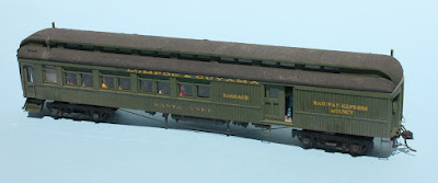
The model I decided to build was a kit passenger car with enough added detail that it could compete for a Merit Award, and indeed it succeeded, at a time when model contests were quite competitive in MCR (and likely still are). Below is an overall view of the car. The removable roof is covered with strips of Kleenex soaked in paint to represent canvas. On this one side, I modeled the baggage door partly open, with a baggageman at the door.

At the time, my layout had been designed to represent a fictitious short line, the Lompoc & Cuyama, extending inland from the Pacific shore near Lompoc, up the Santa Rita Valley, then overland to Cuyama on the Santa Maria River. One town along the imagined route was the actual town of Santa Ynez, and I named the car “Santa Ynez” accordingly. 

The kit for this model was a La Belle HO scale wood combine, and I assembled the body according to kit directions. This involved about 100 wood parts which had to be fitted and glued into a car body. But I discarded almost all the kit detail parts, thinking I could do better. All handrails and grab irons were fabricated with brass wire of various sizes, as was piping on the underbody.

The underbody was a point of emphasis, because it’s often neglected on model passenger cars. I consulted drawings in the 1925 and 1931 Car Builders’ Cyclopedia to develop the information I needed, and once it was modeled, I drew the various systems on the LaBelle kit drawing of the underframe to illustrate what I’d done, for the benefit of contest judges. It shows the air brake system, the Pintsch gas lighting components, and the pressurized water system. Pipe sizes are shown for each system.

The model underbody following the drawing above is shown below. The passenger brake gear is Cal-Scale; essentially everything else (except trucks and couplers and queenposts) is scratch-built. You can click on the image to enlarge it if you wish. 

In addition to this underframe work, my goal was to add a fairly complete and detailed interior. This meant a full set of seats and a moderate number of passengers, along with details in the baggage compartment. In the passenger compartment, I added baseboard heater covers, a complete toilet including paper dispenser, luggage shelves at one end instead of overhead racks, and seats with commercial figures. 

The baggage compartment has a water pump on a pallet, a bicycle, crates, boxes, sacks and parcels, most with tags, plus suitcases and a trunk. A toilet, locker, and a desk with pigeonholes are provided for the baggageman, along with a calendar and fire extinguisher.

Some modelers might react to the interior detail shown above, and think, “Why do all this work that can’t be seen, except with the roof unrealistically off?” The answer, as any contest modeler knows, is to maximize points for construction, detailing, and scratchbuilding. It’s a contest model, that’s all.

This was a lot of fun to imagine, design and build, and it did well in several contests, enough to earn a Merit Award, later used as part of my qualification for the NMRA Achievement Award as Master Car Builder. But this kind of contest modeling is simply not compatible with the time needed to build and maintain and operate a layout.

I’ve often told the story of a time in a regional contest room, when a group of us regular entrants were chatting, and one person said, “I’m starting my layout,” and someone else said, “Guess we won’t be seeing you in the contest room any more.” Of course the new layout builder protested, but most of us knew the comment was right.

Tony Thompson 

Saturday, July 5, 2025

Correcting my mistake: speeder paint scheme

The other day I posted a description of the new HO scale Fairmont M-19 speeders (or motor cars) produced by Ken Harstine. I knew they were Daylight Orange and so painted them. Ken included a decal sheet for diagonal black stripes on the front or wind screen, but as I had not seen photos from my era (early 1950s) of speeders with stripes, I omitted them. The post is here: https://modelingthesp.blogspot.com/2025/07/speeders-or-are-they-motor-cars.html .

Promptly upon posting, I heard from former SP employee Mike Yoakum, who didn’t criticize, just sent me the Common Standard drawing CS 1942, which is shown below. This was adopted in 1946, and I don’t think it could be more clear. Incidentally, note two points of terminology: SP called them “motor cars” in this drawing, though SP paperwork like special instructions and train orders often refer to them as “track cars;” and the front wind barrier is called a “windshield,” though not transparent like the ones we are familiar with on automobiles. It certainly serves to shield occupants from the wind.

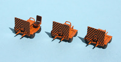
This pretty conclusively shows that stripes were adopted in April of 1946, so obviously I had to go back and correct my speeder models! Now I was really grateful for Ken’s nice decals. Here are the three speeders with properly striped “windshields,” as I now know to call them in SP parlance.

They are now a little more eye-catching on the layout too, as long as they are posed on the track turnouts as headed toward the viewer. I’ve been told that when pulling speeders off the track, crews preferred to swing them so they were facing back toward the track, not away from the track — but not a hard and fast rule.  

Thanks again to Mike Yoakum for correcting my misunderstanding and backing it up with the ultimate authority, a CS drawing.

 Tony Thompson 

Thursday, July 3, 2025

Speeders — or are they motor cars?

 Railroad employees often called them speeders or motor cars; the railroad I model, Southern Pacific, called them “track cars” in official documents. I posted about a beautiful 3D-printed Fairmont speeder in HO scale awhile back (see it at: https://modelingthesp.blogspot.com/2022/07/a-beautiful-ho-scale-speeder.html ) and showed it in place on my layout. It was produced by Yelton Models, located in Niagara Falls, Ontario. 
More recently, a Fairmont M-19 speeder in HO scale was 3D-print produced by Ken Harstine (I believe doing business as Voltscooter), in three versions: with a windscreen and a seat, with windscreen only, and with neither seat nor screen. Below is a photo from Tim O'Connor showing such cars. This view was taken at Beaumont, Texas in 1976. 

The one in the rear in this view is enclosed, like the Yelton one I showed in the post linked in the top paragraph, above. The foreground car, without seat or screen, is the type sometimes called a “gang car,” as it might be used by track gangs. The middle speeder has a windscreen (of a later design including clear windshield in the upper part) but no seat. Note that these cars have fenders on the wheels, an optional feature on Fairmont speeders.

Here is the simplest speeder, much like the “gang car” shown above, with neither windscreen nor operator seat, seen at the speeder shed in my layout town of Ballard. Beyond the shed is an SP concrete phone booth. Like all my speeder models, it’s painted Daylight Orange. Wheels are grimy black.

Addition of a windscreen makes a speeder like the center car in the prototype photo above, but with the early style of a screen only, no windshield. It’s at the speeder pull-out  or turnout near the mainline tunnel on the approach to Shumala on my layout. Note that it does have the handles that a crew can use to manhandle it on and off the track. (I described building SP-style turnouts like this in a post awhile back; see it at: : https://modelingthesp.blogspot.com/2019/01/track-car-turnouts-part-4-installation.html ).

These speeder models are provided with decals for diagonal black stripes on the front. From what I know, these stripes were used in later years, but I have not found a photo showing such stripes on speeders in the early 1950s. Thus my models don’t have them.

Here’s a close-up view from the rear of the type shown above. It’s impressive what has been modeled here; this is a really small model. The width of the windscreen shown below is just 9/16 of an inch.

The third type is like the one above, but with an operator seat. Note the motor controls in the center housing, included on all these speeder models. It’s shown on the pull-out near the depot in my layout town of Santa Rosalia. In the background is the trailer containing the Harbormaster’s office for the port.

These are all nice models for period “atmosphere,” and I can change them from pull-out to pull-out so they don’t become scenery fixtures.

Tony Thompson