Tuesday, April 19, 2022

Updating the car fleet plan: covered hoppers

I have often written in this blog about fleets of freight cars: what kinds of cars were historically present, how one might identify the needs for a particular railroad, or for a particular area on a particular railroad; and how to proportion a model car fleet in a realistic way. Among the posts addressing those issues, and also containing links to all my 2011 posts about my own car fleet, is here: https://modelingthesp.blogspot.com/2013/02/keeping-model-car-fleet-under-control.html . 

 One of the fleet components I have been re-assessing is my covered hoppers. Let me begin by emphasizing that cars of this type were not common at all in 1953, the year I model. They are ubiquitous today, but not in 1953, comprising only a few percent of the national fleet in those days. 

Back in 2011, as I mentioned in the first paragraph, above, I included a covered hopper plan in my fleet summaries (here’s a link to that specific post: http://modelingthesp.blogspot.com/2011/02/choosing-model-car-fleet-6-covered.html ). The dominant cargo carried in covered hoppers in 1953 was cement, by a large margin. Grain carriage was years in the future, and dry chemical shipments were just getting established.

 Accordingly, nearly all my covered hoppers are weathered and waybilled for cement service. An example is below, from Union Pacific’s first class of these hoppers, painted boxcar red. As is obvious, this wasn’t a great choice of color, and all subsequent UP covered hoppers were light gray, along with most of the rest of railroading. The car is being switched at Shumala on my layout, and like all the cars shown in this post, originated as an InterMountain model. (You can click on the image to enlarge.)

But there are a few exceptions. I have rostered several such exceptions, but these are operated sparingly, in light of their relative rarity. Nevertheless, Ed Hawkins and Pat Wider documented a great many different leased covered hoppers, to a wide range of industries, in the Railway Prototype Cyclopedia (RP Cyc), especially Volume 30 (2015). In the photo below, a car leased by North American Car Co. (marks NAHX) to American Potash & Chemical, being blocked for pickup at Shumala, is just crossing Chamisal Road.

Many industrial companies, of course bought their own cars, as also documented in RP Cyc issues 27, 28 and 30. For example, here is a car owned by General Electric used to move glass sand, closely following prototype photos. We see it here in a passing mainline train on my layout.

Finally, the leasing companies kept some cars simply under their own reporting marks for flexibility in assignments. All of the “Big Three” lessors did this (General American, in their covered hopper division, marks GACX; Shippers Car line, under SHPX; and North American, under NAHX). An example is this car from the GACX fleet, seen bringing up the rear of the Santa Rosalia Local in my layout town of Ballard.

This car was one of my “small projects” awhile back (a description is at: https://modelingthesp.blogspot.com/2018/10/small-project-repurposing-covered-hopper.html ).

All these examples offer a change from the far more numerous railroad-owned covered hoppers in the early 1950s, and though all of these are authentic schemes, as I mentioned, I do operate them sparingly.

Tony Thompson


Saturday, April 16, 2022

A 3-D printed freight car, Part 3

 In the previous part, I completed the minor work involved in adding a few details to the Pere Marquette double-door box car produced by Eric Boone. In that post, I also summarized the assignment  history of these cars (auto racks or not, etc.) and showed a prototype photo (you can view that post at: https://modelingthesp.blogspot.com/2022/04/a-3d-printed-freight-car-part-2.html ).

Now the car was ready to paint. I washed the body in warm water with dish detergent, and let it dry thoroughly. You see it below, resting on “paint shop” trucks.

Without clear knowledge of PM paint colors, I wanted to use a generic freight car color. This seemed acceptable because I planned to weather the car significantly. I chose Tamiya Red Brown, TS-1, to paint this car, and when all paint odor was gone, I added a coat of gloss finish for decaling.

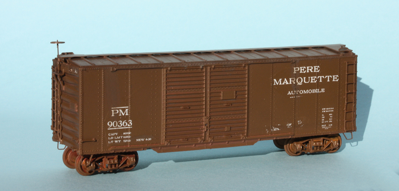
Eric Boone provided a very well-done set of decals for the car, and I followed his advice and added a coat of gloss finish to the sheets to make sure they would perform. as intended. They are a pleasure to apply, nice and thin but with crisp, opaque lettering. Here’s the car, with a few chalk-mark decals to the right of the door.

The model above visibly still rests on my “paint-shop” trucks. The model’s assigned trucks, along with couplers, were installed next, so that they could benefit from the following step. 

That next step was weathering. I pursued my usual regimen with acrylic tube paints, made into washes. The method, along with some details of use, are thoroughly described in my “Reference pages” (see the links at the top right of every one of my blog posts). When satisfied with its appearance, I let the model dry well, then applied a coat of flat finish. The acrylic weathering pigments do adhere, but are vulnerable to a scratch with a tool or fingernail, until given a protective finish coat.

But of course the job of finishing wasn’t done; I still needed to add reweigh and repack stencils. The first step with these is paint patches, exactly as yard personnel painted out the old stencils to give a place to stencil the updated information, with a new date and location for a reweigh or repack. 

I have posted before about how I model these paint patches (see, for example: https://modelingthesp.blogspot.com/2020/07/modeling-paint-patches.html ), and I have also described the results, with a number of model examples (see: https://modelingthesp.blogspot.com/2020/08/paint-patches-part-2.html ). 

The present model would of course need both kinds of stencils. For my modeling year of 1953, the reweigh date would have to lie within 48 months in the past, as that was the AAR rule in 1953. I turned to my usual source of these, some old Sunshine decal sets of reweigh symbols and dates, and applied suitable ones over the “fresh paint patch” decals. I also added route cards.

The car is shown below, being switched at Shumala on my layout, perhaps containing a load of furniture from Grand Rapids, Michigan, one of the purposes for which these cars were built.

This 3D process makes a nice looking car, and a somewhat unusual body style, and I’m glad to add it to my car fleet. The modeling is very easy with the 3D-printed body and underfame. It’s true that some details like grab irons aren’t as fine in cross-section as would be the case with wire parts, but the speed and ease of assembly are the offsetting benefits. I like the car, and it was fun to work with a new (for me) kind of model.

Tony Thompson

Wednesday, April 13, 2022

A 3D-printed freight car, Part 2

 The potential for 3D-printing of entire freight car bodies has been recognized for some time. But the latest one I have seen is remarkable in the amount of detail parts that can be printed on the car body or underframe. I showed those parts as they come from the printer, produced by Eric Boone, in the previous post (see it at: https://modelingthesp.blogspot.com/2022/04/one-piece-3d-printed-freight-cars.html ). 

When the car body is freed from its supports and base, the underfloor is revealed, containing four hexagonal cavities which accept 2-56 nuts, that will in turn accept the truck screws and coupler box screws.

And with both pieces removed, the underlying “forest” of supports from the printing process are revealed. These are fairly brittle, so care is necessary in cutting the parts free. But I found that this goes very quickly, mostly using a sprue cutter on the outer supports, then a utility knife on the remainder.

Eric recommended that as soon as the underframe part is freed from its base, that it be glued to the car body, in case it should have a tendency to warp. I did that, using canopy glue. As soon as that was set, I looked toward the parts I would be adding, brake staff and wheel, and sill steps. For these, I wanted to compare to the prototype, 2000 cars built in 1930, numbered PM 90350–92349.

My first stop was to look up these cars in the superb book by Arthur B. Million and John C. Paton, Pere Marquette Revenue Freight Cars (Hundman Publishing, 2001), which I reviewed in an earlier post (you can see that review at: https://modelingthesp.blogspot.com/2018/01/auto-industry-traffic-part-6.html ). 

Here I learned that the first 1500 cars of this 2000-car group were built by Pullman, with the last 500 coming from Pressed Steel Car Co. and having end doors. Of the Pullman cars, having side doors only, all but the first 300 cars were equipped with auto loading racks, AAR Class XAR. Obviously our model, not having end doors, models one of the Pullman-built cars. Below is a photo of one such Pullman car (C&O Historical Society).

Note on this car that the sill steps correspond to A-Line Style B. Eric Boone’s kit directions suggest Style C, which would indeed be correct for the Pressed Steel Car products but not for the Pullman cars. 

Starting in 1948, Chesapeake & Ohio (having taken over Pere Marquette) began to renumber the cars we are discussing, renumbering most into six-digit numbers groups within the 254000–256000 series. By 1953, when I model, the Official Railway Equipment Register shows that about 500 of the Pullman-built cars in the series we are modeling remained with PM reporting marks. Accordingly, I will so letter my model. For those wanting to letter for C&O, there is a photo of one of these cars in C&O lettering on page 146 in the Million & Paton book. 

One last prototype detail: by 1953 all but a handful of the surviving PM cars of this kind no longer had auto racks, were then Class XM, and were assigned to auto parts service. Therefore, they did not have the white door stripes indicating auto racks, and would have actually looked much like the builder photo above (except the word “furniture” had been dropped).

Last task before painting was to install a brake wheel and staff. I used 0.019-inch brass wire and a wheel from the parts stash (maker not known), and attached them with canopy glue. I will move on to painting and lettering in a future post.

Tony Thompson

Monday, April 11, 2022

One-piece 3D-printed freight cars

 Ever since modelers recognized the potential of 3D printing, whether in resin or other materials, the idea has circulated of making entire car bodies. And a number of commercial projects have ensued, including at least two that I have written about in this blog. One was Southern Pacific Class W-50-3 ballast cars, produced by Robert Bowdidge (described in this post: https://modelingthesp.blogspot.com/2015/10/the-new-dry-creek-sp-work-cars.html ), and the 46-foot GS gondolas, a D&RGW design, offered by Corey Bonsall (described as part of an account of a Collinsville meeting: https://modelingthesp.blogspot.com/2017/07/interesting-products-at-collinsville.html ). Both are open-top cars.

Recently my friend Joe Binish in Minnesota let me know about a one-piece Pere Marquette box car that Eric Boone has produced. I was immediately interested, and Joe sent me sample parts. Eric gave me permission to show the car parts and to mention that he may decide to offer these as kits. 

When I received the parts that Joe sent, I was immediately impressed, not to say amazed. I show below the underframe part, with all the “runners” needed to produce the desired piece, complete with brake gear and rigging. This is printed from the flat plate at bottom, upwards to the final product on top.

Even more impressive is the car body, with radial roof, Dreadnaught ends, correct 6-foot doors, free-standing ladders and rungs, even open grab irons. Again, this is printed upwards from the flat plate at bottom.

I was perhaps most impressed by the  running board, not only standing free of the roof but also prototypically thin, and with corner grab irons.

It perhaps goes without saying, that there is considerable process refinement needed to arrive at a design which can create all these free-standing parts. You can sense that in the photo above, with the “runners” to the ladders. This view of the car’s B end, with brake platform included, along with running board end supports and the side and end ladders, illustrates the point.

I will proceed with the model in a future post. But once the parts are removed from the runners, all that needs to be added to these two pieces are the brake wheel and staff, stirrup steps, and of course trucks and couplers. Eric has even made decals for the car, and I’ll show the prototype car in the next post.

Tony Thompson

Friday, April 8, 2022

Getting the car you want, Part 2

 I began this series of posts with a description of a particular goal I had, to add a car representing a portion of a number series of PFE Class R-40-10 steel reefers to my fleet. There are both research and modeling dimensions to this task, and I outlined both in my first post (you can read that post at: https://modelingthesp.blogspot.com/2022/03/getting-car-you-want.html ). 

As I always do with house cars, I chose to add weight to the car with 5/8-inch steel nuts, attached inside the body with canopy glue. But before doing that, I drilled and tapped both the bolster holes (for truck screws), and the coupler box holes, for 2-56 screws. The reason to do that first is so I can avoid covering either hole with the steel nut. In the photo below, you can see at the right of the photo, that both holes are visible, thus not covered.

I am sure modelers will immediately also notice something else in the photo above: the body is warped, with sides bulged outward.  I corrected this when the roof was applied. I made sure the roof fitted correctly, then applied heavy rubber bands to hold it in place, and allowed styrene cement to “wick” into the roof-body joint all around the car. This is not the order of application of parts called out in the instructions, but in this case, I wanted to get the body corrected.

Next, I want to show the information available for this class of PFE cars, from pages 434-35 in the PFE book (Pacific Fruit Express, 2nd edition, Thompson, Church and Jones, Signature Press, 2000). The table below is just the Class R-40-10 portion. The heading is a hand-lettered heading from the original PFE document that was the source of the information (now at the California State Railroad Museum, or CSRM), added here to the table. You can click to enlarge the image to help in reading it.

The group of cars I want to model are in the last three lines of this table. Two additional notes: “SRE Co.” refers to the Standard Railway Equipment Co., and the numbers with the truck listings are the PFE drawing numbers. The handbrakes listed for all the 44,000-series car numbers are either Equipco or Miner, and Kadee makes excellent versions of both, so I will choose the one that goes with my car number.

As I stated in the previous post (link in the first paragraph of the present post), these cars were all built with wood running boards, but in 1939, PFE conducted an experiment with the then-new steel running boards from Apex, and quickly concluded that these were superior to wooden ones. (This was long before the AAR would order in 1944 that henceforth, new cars would have running boards “other than wood.”)

Below is a 1939 photo of one of the Class R-40-10 car in this experiment, shown at the Roseville shops of PFE (PFE photo, author’s collection). One of the five cars chosen for this experiment was PFE 44214, a car number I could choose for my project.

Note also in this photo, the clear view of the separate hatch plugs, hinged at a lower point than the hatch covers, and thus at a different angle. Note also that these hatches are latched as far open as possible (the top of the latch bar), yet they are not at a very big angle.

Repairs and upgrades to PFE cars were all recorded on individual “car cards,” 5 x 7-inch pre-printed cards filled out and stored by the shop. Many of these cards survive at CSRM. I showed examples of these in the PFE book, pages 435 and 436. For Class R-40-10, such replacements of the original wood running boards with steel boards are recorded as early as 1944, and continued for modest numbers of cars until 1950, at which time most of the class was reconditioned.

Since my InterMountain kit for the R-40-10 car I am building has the two-herald paint scheme, in use from 1946 to 1948, I would be modeling a car that might or might not have received a steel running board. It also might or might not have received retrofitted fans. More on that, and other kit completion details, in a future post.

Tony Thompson

Tuesday, April 5, 2022

Adding a UP automobile car

 In the previous post, I described an update to my freight car fleet planning for automobile cars on my layout. As I mentioned in that post, this updates a descriptive analysis I posted back in 2011. In particular, I noted that my present car fleet lacks a 50-foot Union Pacific auto car. To read that post, see: https://modelingthesp.blogspot.com/2022/04/evaluating-car-fleet-part-2-automobile.html .

As it happens, I have a kit for such a car in my stash, a Proto2000 kit with end doors, modeling UP Class A-50-17. The class was built by UP at Omaha in 1941-42, and had end doors.  Other prototype specialties included W-corner-post Dreadnaught ends, Equipco hand brakes, and wood running boards. Clearly it was time to build this kit. 

(For UP prototype information like this, see Terry Metcalfe’s excellent book, Union Pacific Freight Cars, 1936–1951, Metcalfe Publications, Englewood, CO, 1989.) The dates in the book title refer to built dates.

Below is a photo which, though not a great image, is enough to illustrate the main feature of Class A-50-17. It’s taken from from the Protocraft Decals website ( https://www.protocraft.com/category.cfm?ItemID=10295&Categoryid=39 ). In particular, note the “tabbed” side sills. These 250 cars were numbered UP 161200–161449.

For many modelers, the first issue to be addressed with UP freight cars is lettering, and this is well covered in Terry’s book. Until 1936, UP cars had white Roman lettering, without slogans. In that year, they introduced the familiar slogans, “Road of the Streamliners,” and “Serves All the West,” slogans possibly initially in white, but very soon changed to yellow. In June 1939, the Roman lettering was replaced with sans-serif or “Gothic,” still white or yellow. That is the scheme you see in the photo above. In mid-1947, all lettering was changed to yellow.

The Proto2000 kit is in the 1939 paint scheme, correct for a 1941-built car, which means that I will weather it a fair amount for my 1953 modeling year. The car body, as it comes in the kit, happens to have straight side sills, but is cleverly designed with recessed areas on the inside of the body, indicating where to cut to remove material, if a tabbed sill is needed, as with this car (see prototype photo). I did this with a hobby knife to score the cuts, then small files to clean up.

Next, let me address an additional issue with this or any freight car kit. I mentioned above that the prototype cars had Equipco hand brakes. To my surprise, if not astonishment, the kit brake wheel is in fact a late 1930s model Equipco brake wheel. I show the kit part below, in the sprue.

How do I know what this brake wheel is? I consulted Patrick Wider’s superb article in Railway Prototype Cyclopedia (“Freight Car Hand Brakes – 1920s to 1950s”), in issue no. 10 (2004). In it, he showed the photo below, which I concede does not match the Proto2000 wheel exactly, but it’s certainly similar, and the kit part does have six spokes and six holes in the interior dish. (The photo is from Equipco, division of Union Asbestos & Rubber Co.)

Many transition-era modelers understandably think of nothing beyond Ajax brake wheels when building a model, and understandably so, as it was the most widely sold handbrake product in the immediate years after World War II. However, I show that wheel below (also from Wider’s article), just to illustrate that the two prototypes are considerably different. Note also that the gearboxes of the two makes (behind the wheels) are different in shape.

I will of course use the kit wheel on my model, with some pleasure in being able to use the correct part.

There are additional issues to be solved in this kit (beyond of course the mere following of kit directions), and I will come back to those in a future post.

Tony Thompson


Saturday, April 2, 2022

Evaluating the car fleet, Part 2: automobile cars

As I mentioned in the preceding post, back in 2011 I updated all my car fleet plans by car type. Some of them have changed little, despite adding more cars (I think mostly in accord with plans).  I gave the example of gondolas (see that post at: https://modelingthesp.blogspot.com/2022/03/evaluating-car-fleet-anew-gondolas.html ). But there are exceptions. This post is about one car type that is an exception: automobile cars.

For many years after the 1920s, the ARA and then the AAR classified all box cars with double doors as “automobile cars,” regardless of actual assignment, intended use, or the presence of special equipment such as auto loaders. It just meant a double-door box car, nothing more.

This is well illustrated by Southern Pacific, which classified all its double-door box cars in Class A (automobile), even though only a minority of the fleet was equipped for or assigned to automobile traffic. That includes auto parts as well as assembled automobiles. This was just as AAR intended.

My post in 2011 about automobile cars described the balance I believed needed at that time. Here is a link to that post: http://modelingthesp.blogspot.com/2011/02/choosing-model-car-fleet-4-automobile.html ). I did discuss auto parts and assembled automobile routing in some detail.

To summarize, one indication of the cars that would be needed in any automobile car fleet is the route(s) cars would follow, from the upper Midwest, particularly Michigan, where so many auto parts, as well as assembled automobiles, were manufactured, to the railroad you model.  For Southern Pacific modelers, that means primarily the Overland and Golden State Routes. 

For the Overland Route, there exists a very helpful magazine article by Mark Amfahr, “Bay Area Auto Shipments in the Postwar Years,”which appeared in the Spring 2016 issue of the The Streamliner magazine (UP Historical Society), pages 6–13. It contains fascinating data, as shown below.

The reason for these various railroads’ cars, of course, is that most railroads joined into pooling arrangements, usually on the basis that each railroad contributed  the same proportion of the needed number of cars, as their proportion of the total miles distance in the route. 

To illustrate one aspect of this traffic, the 1950s photo below (UP Museum, courtesy Mark Amfahr) shows yard clerks at Council Bluffs attaching a route card to an Erie 40-foot double-door box car containing assembled automobiles. Note that the route card reads “1B,” a UP blocking code indicating priority transfer to SP at Ogden. 

Returning to the graph above, it shows that I certainly need DT&I, Wabash, New York Central, PRR, GTW, and SP cars, all of which are in my auto car fleet. In the previous post on automobile car planning (link shown in the fourth paragraph of the present post), I showed a number of my SP auto car models. I’d like also to show models for some of the other railroads shown in the above chart. Below is the tail end of a Los Angeles-bound auto-parts train, about to arrive at Shumala on my layout.

The models shown above are DT&I 13167, an ancient Athearn metal model, obviously similar to the familiar Pennsylvania X32 cars, and Wabash  45218, an Overland brass model. Note the caboose, incidentally, with its vermilion ends: all of of SP’s pre-1960 bay-window cabooses were built that way (for some background, see: https://modelingthesp.blogspot.com/2022/02/modeling-sp-cabooses-part-4.html ). 

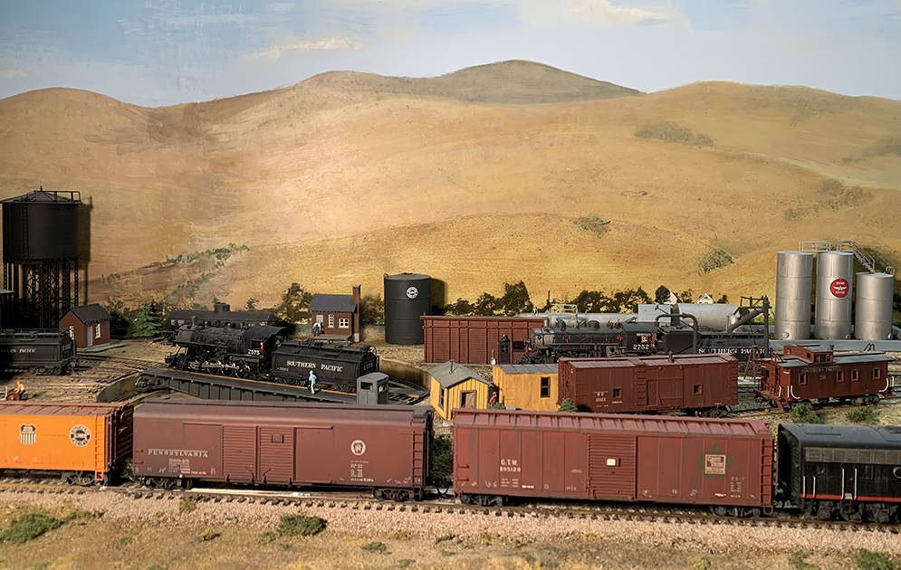
Some additional cars are shown below. Here we see two cars right behind the power on today’s Golden Gate Manifest (GGM), passing the engine terminal at Shumala. The cars are Grand Trunk 595128 (a Proto2000 model) and PRR 58845, Class X32A (a Railworks brass model). Both are in auto parts service, and are returning empty westward from Southern California auto plants, heading for the Overland Route.


I mentioned the specific mainline trains in the foregoing photo descriptions to emphasize that I try to maintain a connection to SP’s Coast Route traffic, even though I can only do so with passing trains, moving from staging onto the layout, and back to staging. For me, this is part of the interest in including the SP main line in my layout.

I have not mentioned Union Pacific automobile cars in the foregoing, but the graph above clearly shows that I need UP cars as part of the auto car traffic to and from the Overland Route. As it happens, my fleet currently only contains a 40-foot auto car.  Obviously a 50-foot car should be added, since the graph shows approximately equal numbers of 40-foot and 50-foot cars in the traffic.

I will return to the creation of a UP 50-foot automobile car model to be part of this traffic in a future post.

Tony Thompson