Thursday, October 19, 2023

The new Class One flat car

 Many of you will have seen the announcements by a relatively new model manufacturer, Class One Model Works, for a 58-foot heavy-duty, depressed-center flat car. (You can visit the Class One site to see these models at: https://classonemodelworks.com/product-category/model-type/flat-cars/ .) Several railroads built very similar versions of this car, because General Steel Castings Corp. (GSC) produced a one-piece steel casting for the entire car. This of course made a very strong and durable car body.

Below is an example of one of these 58-foot GSC frames, produced under the “Commonwealth” name, whitewashed for the photo (GSC photo for Southern Pacific, Steve Peery collection).

Either a car builder or the railroad’s own shops could add brake gear, desired decking, and suitable trucks and couplers to complete the car, a straightforward job for most railroad shops. One of the interesting things about the flat cars produced with these body castings is that many of the railroads chose to use a heavy-duty 6-wheel Commonwealth truck produced by GSC, a distinctive-looking truck (GSC photo for Southern Pacific, Steve Peery collection).

As you can tell from my photo credits, Southern Pacific was one of the railroads that bought these cars, with these trucks. But Class One is not offering an SP version. I have an idea why not. 

The Class One models offer either a wood end deck or an open-grate end deck, and all cars have the end-to-center transition area open, with the slots showing (see the frame photo above). But SP covered the transition-area slots with steel plate, and welded steel plate onto the end decks also. This rather vertiginous photo, taken from the overhead crane at the T&NO shop in Houston (SP photo, Steve Peery collection), shows this, though this is a slightly different car from those shown above.

That of course raises the very interesting question of whether the Class One model can be modified to match the SP cars shown in these photos. I am still contemplating that option. But to assess whether that would be feasible, I went ahead and bought one of their cars, Erie 7265, a car built in 1948. Like all the cars, it has the Commonwealth trucks (they are roller-bearing trucks, not correct for the Erie car in its original state.) It’s a very nice model and will certainly be going into action on my layout, pending truck correction. This model has the wood end decks.

I even admire their shipping box for the cars, a crate-like look that I show below. Inside, the model is securely positioned at an angle to the short directions of the box, and arrived in perfect condition.

I will return to the question of whether I can or will modify one of these cars for Southern Pacific in a future post. But I do know how to back-date a roller-bearing truck to plain bearings, as I did for my helium car model some years ago (see the post at: https://modelingthesp.blogspot.com/2012/04/helium-cars-part-1.html , scroll down to the bottom). I may do the same for the Erie car shown above.

Tony Thompson

Monday, October 16, 2023

Upgrading a Red Caboose SP stock car

Over ten years ago, Red Caboose released an HO scale model of a Southern Pacific stock car, representing Class S-40-5. This was a large car class, as stock cars go, more than 800 cars. Along with Class S-40-4, the -5 class represented a standard stock car body design, differing only in whether their underframes comprised one or two center sills. Succeeding classes S-40-8 and -9 were all but identical, representing the great bulk of SP’s stock car fleet. Many survived into the 1950s. 

For these reasons, the choice by Red Caboose of Class S-40-5 to model is a good one. A post from some time back summarized how they can be upgraded (the post is here: https://modelingthesp.blogspot.com/2015/07/modeling-sp-stock-cars.html ). The primary issue to be addressed is trucks. Red Caboose supplied these models with T-section trucks, a design much used by SP between 1912 and 1925; but unfortunately, not used for stock cars except for some much later rebuilds.

Instead, SP applied Vulcan trucks to most of its stock cars, and as I know from perusal of the SP Car Ledgers, there were no examples of T-section trucks ever applied to Class S-40-5 cars. Shown below is a prototype photo of a Class S-40-5 car, taken from my book, Volume 1 in the series Southern Pacific Freight Cars, entitled “Gondolas and Stock Cars” (Signature Press, 2002). It’s an SP photo, taken at Dunsmuir in 1928, from the Shasta Division Archives. Like the rest of its class, it has Vulcan trucks, and still has the periods between initials in the reporting marks, correct until 1931.

Luckily, Kadee makes a very nice Vulcan truck. When I wrote the post linked in the paragraph above, they only offered the Vulcan design in a “sprung” truck with working springs. Subsequently, they have added an “HGC” version, with HGC standing for “high gravity compound” as the truck material. 

More importantly, the HGC trucks have a molded sideframe, thus without the far-too-open “real springs” of the sprung truck (for more on those issues, you might want to look at my MRH article, September 2016; some blog commentary is at: https://modelingthesp.blogspot.com/2016/09/my-column-on-trucks-in-september-mrh.html ).

Below is one of the Red Caboose stock cars, with truck changed out to Kadee Vulcans. Note that the 1946 introduction of spelling out the road name instead of using the initials “SP,” has caused a rather long board to be required for that road name.

But in the early 1950s, one sees, in prototype photos, evidence that some shop repaints of SP freight cars did not bother with that full road name but just applied the initials (the pre-1946 practice). In 1953, the change back to initials became official. On stock cars, this led to the interesting result of that long board remaining, but only initials lettered on it. 

Below is a prototype example, no doubt taken to record the pair of new Trainmaster locomotives, 4810 and 4815, at Carrizozo, N.M. where they first went into service, by Lewis Harlow (Bob’s Photo collection). But this June 1955 image also records SP stock cars 70998 and 73970, both with long “road name boards” now occupied only by car initials. (You can click on the image to enlarge it.) Note also that the deep color on the stock cars suggests that they have probably been relatively recently repainted.

Lettering like this was included in the Red Caboose production of the Class S-40-5 cars, such as my model shown below, SP 73691. But in this photo, the original T-section trucks are still present, despite my having weathered the car and added chalk marks, route cards, and repack stencils. Given that the replacement of the spelled-out road name with initials was only from 1953 onward, and the discontinuance of the 1-inch stripes above and below the reporting marks was in January 1952, I tried to maintain most of the original color in the weathering, as the photo above suggests.

Of course, the truck issue is easily corrected. I simply replaced the Red Caboose trucks with those Kadee HGC Vulcan trucks, product number 1573 (with the 0.088-inch wheel treads), and added a little grime to the sideframes. I also replaced the lame couplers supplied by Red Caboose, with Kadee “scale head” whisker couplers, my de facto standard these days.

The car can now be used in layout operating sessions as a fully prototypical SP stock car, and its lettering is consistent with the model’s reweigh date of March 1953. I like variety in my stock cars, and the “remnant” long road-name board on this model provides that.

Tony Thompson

Friday, October 13, 2023

Modeling SP passenger cars, Part 18

In the previous post, Part 17, I showed the completion of painting and striping applications to the two cars of different floor-plans that I am working on, a 13 double bedroom car (13 DB) and a 4 double bedroom–4 compartment–2 drawing room (4-4-2) car.  You can read that post at this link: https://modelingthesp.blogspot.com/2023/09/modeling-sp-passenger-cars-part-17.html .

In the previous post just cited, I mentioned the problems of decal availability. I do have one of the Champ Lark sets (Champ PH-110), and could go ahead with lettering. This represents compromises. The Champ lettering is white rather than SP Lettering Gray (though on these gray sides the difference is minimal), and the lettering does not have the 1/8-inch wide black outline that SP continued to apply until 1956. In HO scale, those compromises aren’t crushing.

There happens to be an alternative. Todd Osterberg has recently completed artwork for several Southern Pacific streamlined passenger trains, including the 1941 Lark. These are excellent renditions and do include the outlining that was in use in the year I model, 1953. These decals will be available in a few weeks or so, and will be sold via Owl Mountain Models (their website is at: https://owlmtmodels.com/ ; that’s not a link to the decals, as they aren’t up yet). Here’s a sample. You can click on the image to enlarge it if you wish.

The car number shown, SP 9352, is the number I will apply to my 13 DB car.

The background on the locations of lettering on Lark cars, and the car numbering for the cars modeled, was described in a previous post (see it at: https://modelingthesp.blogspot.com/2023/05/modeling-sp-passenger-cars-part-15.html ). The first interesting lettering pattern for these two cars is for the 4-4-2, which had the distinctive small windows in pairs for the upper berths in the compartments. The prototype photo below (Lawson K. Hill, San Francisco, August 1953) illustrates the lettering part of the problem: the road name had to be located well off-center to clear those windows.

This was of course how I lettered the model, adding the car number below the Lark emblem. The car shown above is SP 9106, and I chose that number for my model. Below you see the same side of my model 4-4-2 as in the above prototype photo (the bedroom side). The off-center road name is certainly distinctive. Note, incidentally, that the remnant skirt seen above is reproduced on the brass car side used for this model.

You may also note above that a diaphragm face plate has been attached to the car end, and brass wire used to represent the diagonal stabilizer bars that are so visible on prototype diaphragms (for more discussion and illustration of this point, see my post: https://modelingthesp.blogspot.com/2021/06/passenger-car-diaphragms-part-3.html ). Here’s a better view of such model bars, shown on an AHM 10-6 car (repeated from the preceding post in the series, cited in the first paragraph, above):

Note in the photo above that there are handrails either side of the door. At the other end of the car, the blind end (no vestibule), there was a single handrail and a step for the use of brakemen or switchmen. The photo below (Pullman-Standard photo, Rob Evans collection) shows this on a brand-new 13 DB Lark car in March 1941. The handrail was cadmium-plated, the step was painted body color.

On some of my streamlined car models, I have added the handrails with wire; on others with a length of 0.010-inch styrene rod.

Another issue that arises with cars like these is that they were “all-room” cars, that is, all accommodations in the car were rooms with doors. That means that you could never see through such a car (unless someone was just opening a room’s door). But these AHM cars have no such interior. I have made full-length view blocks, using 0.020-inch styrene sheet, braced with 1/8-inch square styrene strip along the bottom (which also provides a gluing surface). 

The side that will be toward the aisle-side windows should be a passenger interior color (I chose an ivory shade), and the back of it (lower one below) is dark gray. That means that from the bedroom side of the car, you won’t be able to see anything inside, which is realistic. I might mention that I once went to the trouble to draw room doors with pencil on an aisle-side view block. However, these were almost impossible to see through HO-scale side windows, and I haven’t ever repeated the exercise.

These need to be installed inside the car relatively close to the aisle-side windows. Aisles in these cars were only about 30 inches wide, so that scale distance is appropriate. I attach them with canopy glue, taking advantage of the bottom bracing. Below is the aisle side of the 4-4-2 car with view block installed (this side of the car was lettered with the Osterberg decals).
With lettering well along and view blocks installed, the main remaining task is to deal with diaphragms. I want to install full-width ones on one of these cars, and will return to that topic in a concluding post.

Tony Thompson

Tuesday, October 10, 2023

Trackwork wars, Part 7

 Most of my layout maintenance challenges have been electrical, not issues to do with trackwork, thus the long series of posts called “electrical wars” (to find those posts, use that term as the search term in the search box at right). But trackwork issues do arise, and this post addresses the latest one of those.

As it happened, this latest issue arose at the same switch (at the lead into all the industries at East Shumala on my layout) as the recent post in the “electrical wars” series. That post, with some views of the trackwork, can be seen here: https://modelingthesp.blogspot.com/2023/10/electrical-wars-part-21.html .  

The problem was derailments in the same area as the electrical glitch, so it required a separate investigation. I discovered that the crosswise level of the track had deteriorated, perhaps due to shrinkage or warping of the support materials underneath this area. But the job was to correct the track.

I used a tool I have shown before, a transparent plastic “plank” on trucks. It permits you to see what is happening underneath it in areas of derailments or other problems (see that post at: https://modelingthesp.blogspot.com/2019/11/trackwork-wars-part-4.html ). Here’s a photo of it in the affected area. A small level is resting on it.

Since the “plank” is kind of tippy, one needs to take care in making sure the vehicle is itself resting flat on the truck bolsters, so that the small level reflects the state of the track, not that of the plank. 

Right in the area shown above, the track into East Shumala was found to be tilted downward toward the camera, that is, the nearer rail was significantly lower than the far rail. You can see this in the level’s bubble below.

Having demonstrated the defect, the next step was to correct it. My experience has been that if you slice into the material under the track, it tends to raise the track. My preferred tool for this is a putty knife, as you see below, with the “digging” in progress. I insert the tool under the track and gently pry upwards. Then check the level and, if needed, pry a little more.

Here is the result. It only took a few tries at prying to achieve this, and rolling stock over this area did indeed perform dependably.

I dislike having to confront it, but there are now a couple or three areas on the layout where support underneath has shrunk or sagged or something, leading to track that has a dip in it, or is not crosswise level. I am quite sure I didn’t install it this way, and tracking problems over these sections have only emerged recently and had to be corrected. I’ve learned that I just have to keep after these kinds of things.

Tony Thompson

Saturday, October 7, 2023

Route cards, Part 26: car movement

 In a lengthening series of posts, I have been showing the fascinating (at least to me) variety in grading cards and route cards used by different railroads, all from the Michael Litant collection. Grading cards were used after an empty freight car had been inspected, and the card identified what class of loading could be put into that car. Route cards directed car movement, usually to an interchange or specific yard track. But some cards, as seen in the present post, directed other movements.

[Previous posts about grading cards or route cards can easily be found by using “route cards” or “grading cards” in the search box at right.]

I will begin with a couple of straightforward cards, intended to direct cars for repairs. The first, a New York Central card, is interesting in that one side directs a car to be moved to a shop for repairs when empty; while the other side directs immediate repair, probably for cases where the car could not or should not be moved. It is 3.5 x 8 inches in size and has not been filled out.

A similar card from the Denver & Rio Grande Western is 4 x 8.5 inches, and is dated June 4, 1968. Here one may assume that the red-color side is the equivalent of the “Shop at Once” side of the NYC car above. That is also the side filled out. The car number indicated is 3481 but no initial is shown. That may, of course, indicate that it was a Rio Grande car, but at that time D&RW had no cars with that number. It may be an abbreviation.

A second type of these “directed movement” cards directs something like a car needing inspection, as with this example from the Chicago & Northwestern.It is 3.5 x 5.5 inches in size, and the back is simply a stamp, “40 St.,”, probably a destination to which the car should go next. It is not filled out.

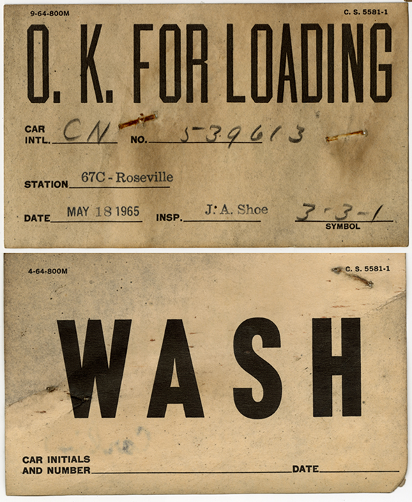
We can go further with this, in the case of a Southern Pacific card filled out at Roseville on May 18, 1965. Though it states the car can be loaded, no grade is given. The other side would direct a car to be washed out inside. It is a 3 x 5-inch card. The car is CN 539613, a 40-foot, 65-ton box car. I don’t know the meaning of the “symbol,’ 3-3-1, but could be a block of cars in the yard.

A similar card is this from the Milwaukee Road, directing a car to be weighed. It is 3 x 4 inches. The interesting side, though, is the reverse, originally blank but stamped “Miller Brewing Co. 4101.” The car identity isn’t clear (U 27013) but the logical inference is that this is a URTX 27013, a 50-foot refrigerator car, an RBLcar (bunkerless and insulated, with loader equipment).

Finally, a pair of placards obviously intended for the placard board, not the route card board, and the two car sides would probably get one of each. Each is 4.25 x 7 inches in size. The source is the Hoerner-Waldorf Corporation of Montana, and the cards are dated Jan. 2, 1973. A good example of a shipper-supplied cards instead of cards supplied by the railroad.

These cards are a kind of variation in the typical route cards, in that they direct movement in a somewhat different way. They certainly add to the wide variety of card types and designs that were in use.

Tony Thompson

Wednesday, October 4, 2023

Layout operating session no. 85

I note in my layout records that the operating session I hosted on Friday,  September 29 was the 85th on the present version of the layout (adding to a few dozen on the previous version). As it happened, this was kind of a special session, organized to take advantage of a visit to the Bay Area by Bob Hanmer, well-known layout owner and operator from Chicago. 

Having enjoyed operating on Bob’s excellent GN and DM&IR layout in Chicago during Naperville RPM meets in several previous years, I was delighted to help with hosting. My session was one of three organized so Bob could attend. The first session was at Jim Providenza’s Santa Cruz Northern, and my session was second.

One thing that I revived for this session, that hasn’t been included in the last half-dozen or so sessions, is the operation of the ballast train. I described the idea behind this, and showed the company “Bulletin” provided to crews and agents to make them aware of the operation, in a previous post (you can read it at this link: https://modelingthesp.blogspot.com/2019/11/more-operating-sessions.html ). The idea is that re-ballasting is taking place elsewhere on the division, and this train is picking up empty ballast cars that have been spotted in different areas as work progressed.

The crew for this session, in addition to our guest Bob, were Dave Falkenburg, who teamed with Bob, and John Rodgers and Richard Brennan. Below is a view of Bob and Dave (left to right), operating at Ballard. Bob was the conductor here,  and Dave the engineer. Looks they are switching the area north of the depot, judging by the refrigerator cars being moved at this point.

Meanwhile, at Shumala on the other side of the layout, Richard and John (from left to right) were working through the switching they needed to do. At this point, Richard was the conductor (as may be evident from his thoughtful expression) and John was the engineer. I’m not just blowing smoke about that “thoughtful expression.” I have watched many crews switch the first shift at Shumala, and this was one of the best-organized jobs I have seen.

The next day, Saturday, there was an operating session at Paul Weiss’s very large and impressive Central Vermont layout, and Bob participated, with several different train assignments. Here he is crewing a passenger train, CV’s No. 1, with Cydney Abatecola (at left). You can see their train at far right, passing alongside East New London yard. (I was yardmaster here.)

It was great to host Bob Hanmer for these sessions, and the varied styles and requirements of these three layouts were bound to have been a varied and interesting experience for him. And the rest of us had a good time too!

Tony Thompson

Sunday, October 1, 2023

Electrical wars, Part 21

This particular post in the series isn’t really one of my classic confrontations with an electrical failure on the layout, but more of the maintenance that needs to be done on the electrical front. (If interested, you can easily find the past members of this series by using “electrical wars” as the search term in the search box at right.) Still, it’s definitely electrical, so I’ll include it.

In preparing for an operating session, I routinely clean all track, then operate locomotives through all switches. Inevitably there are one or more switches for which the point rails aren’t making adequate contact with the stock rails. Of course, the obvious remedy is to clean the inside of the stock rails and the outside of the point rails in the areas where they contact.

In the photo above, taken at the switch into the industrial spurs at East Shumala on my layout, I am using an abrasive stick to clean the areas mentioned. This is just an ordinary emery board, as you see below; as I wear out and dirty the ends, I cut them off to bring fresh abrasive to the end. Over time, of course, the board gets shorter and shorter.

Often this kind of cleaning is sufficient to take care of the problem. But sometimes, as in the case of the switch I am showing here, it did not. In that case, it’s essential to check what’s going on, using a multi-meter. With that tool, I was able to isolate the problem quickly.

What I found was that the rail connection leading into the switch was not conducting consistently. (Yes, this was one of those super-annoying intermittent faults.) It was the rail nearest the camera in the view above. A little work with moving the rail joiner restored consistent conduction. Had that not worked, I would have soldered a jumper wire across the joint. 

Then, of course, the ultimate testing tool is a locomotive. Meters can mislead,  but not locomotives. (Of course, I am just talking electrical here. Locomotives can have faults of their own, like dirty wheels, but if the locomotive is running well, it’s the final test of track.) So after any work like this on a switch, I run a locomotive back and forth at different speeds to verify that the problem is fixed.

With this work, I restored dependable electrical behavior in this switch, needed for an upcoming operating session. As it turned out, this electrical problem, though quite real, was not the entire issue with this switch, but dealing with the remaining problems, which weren’t electrical, will be the subject of a separate post.

Tony Thompson