There have been all kinds of wooden crates offered in HO scale over
the years, along with barrels, boxes, drums, and trunks. But by the
1950s, when I model, the use of corrugated cardboard cartons was
becoming established, and many products were so shipped. On the various
loading docks of the industries on my layout, I would like to be able to
show such cartons. Surely there is a practical way to make these
details.
This idea had percolated around in my head for some
time, until I had one of those “Eureka!” moments. Ordinary brown paper
bags are exactly the same color as most corrugated cardboard. They do
come in a variety of weights, and for this use I prefer the lighter or
smaller bags, like the one below. It’s about 9 inches long and the width
shown is about 5 inches.
All that is needed here is to cut out and fold up some carton-like shapes.
The first step is to decide what approximate size you want. Let’s say you choose a carton that is 2 feet by 3 feet by 4 feet. A simple drawing can be laid out in seconds. It might look like this, with dimensions in scale feet:
To assemble this kind of box, flaps to be glued are useful, and one can add them (shown shaded below) in somewhat arbitrary shapes. The flaps don’t have to be trapezoids, and in fact real cardboard boxes have them as rectangles. For a box shown as partly open, the flaps must be rectangles, But these trapezoids are just easier to assemble, if the final box is to look closed.
I omitted flaps on one side, thinking that that side could be the bottom of the box.
This kind of shape is easily cut out with scissors, and when all folds are made, the rough box, ready to be glued, looks like the photo below (a test in white paper).
All folds need to be crisp and fully 90 degrees. Then glue the flaps — I use canopy glue. The process is a little like origami, but with patience does work. If the first box isn’t great, keep practicing (ask me how I know). Here’s a brown-paper box of the dimensions shown in the sketches above, and also a smaller box ( 2 x 2 x 3 scale feet), glued so the flaps are open, as with an opened and discarded box.
If you find difficulties getting boxes to stay square, you might try a heavier-weight bag for the raw material. I have learned to work with the light paper, but some may prefer something stiffer.
Many shipping boxes carry the names and emblems of the shipper. I have experimented with logos of appliance manufacturers, for example, as instances where a large carton might be used. Such logos can be added in several ways, but I won’t get into that in the present post.
These boxes are quick and easy to make, to any desired size, and are a good scenery detail to include at suitable places on the layout.
Tony Thompson
Friday, September 29, 2017
Tuesday, September 26, 2017
Punch list? What punch list?
The marvelous TSG video of Jack Burgess’s layout, and incorporating an extensive interview with Jack, is well worth viewing for anyone who hasn't seen it. It can be purchased as a DVD for anyone who would like to own it (you can visit TSG Multimedia at: https://tsgmultimedia.com/product-category/dvds/ ), and the full 43-minute video can also be viewed on YouTube (here is a link to that video: https://www.youtube.com/watch?v=EHGkZHLqALY ). Jack’s re-creation of the Yosemite Valley Railroad deserves attention from everyone.
What does that have to do with my post title, about punch lists? About six and a half minutes into the video, Jack describes having responded to the then-upcoming NMRA National Convention of 2011, to be held in Sacramento, with the thought that he ought to get more of the layout done for visitors. When he looked over his list of remaining things to be done, he realized he could complete it all, and found himself one day checking off the last item on his to-do list. At that point, as Jack puts it, the layout was done.
This made me think a bit. Not because my layout is that close to done, but it’s not extremely far off either. I do write punch lists from time to time, but usually ones that are conceived far more narrowly. That raised the possibility of seeing if a list like Jack’s was practical: everything I want or intend to do to complete the layout.
Like most people, often when I’m busy I will jot down an “immediate“ list to work on. It might look like this recent one:
You can see that I have written various things on the list after it was first made, everything from crossing out the tasks already done, to adding more tasks, along with some dimensions on something that I already forget what. This is an “everyday” kind of list, familiar to practically everyone.
I have long maintained (and of course updated) a longer-term list of things I would like to get done on the layou. This is kind of a running list of things I need to do, but not immediately. Here is an example of a past list, which happens to be from November 2014,
More of the tasks on this list have now been completed, beyond what is crossed out above, in the time since I last used it to direct my work on the layout. But even as an old list, it illustrates the point.
But whether current or not, this is a very long ways from a “finish the layout” punch list. That may come down the pike one of these days, but right now I have lots still to do, and feel no urgency to do so. Much as I admire Jack Burgess — and his ability to declare his layout “done” — I am by no means close to reaching that point, and I don’t foresee a punch list like Jack’s anytime soon. And since I host several operating sessions a year, the layout is already doing its most important job — serving as the foundation for realistic 1950s SP operation.
Tony Thompson
What does that have to do with my post title, about punch lists? About six and a half minutes into the video, Jack describes having responded to the then-upcoming NMRA National Convention of 2011, to be held in Sacramento, with the thought that he ought to get more of the layout done for visitors. When he looked over his list of remaining things to be done, he realized he could complete it all, and found himself one day checking off the last item on his to-do list. At that point, as Jack puts it, the layout was done.
This made me think a bit. Not because my layout is that close to done, but it’s not extremely far off either. I do write punch lists from time to time, but usually ones that are conceived far more narrowly. That raised the possibility of seeing if a list like Jack’s was practical: everything I want or intend to do to complete the layout.
Like most people, often when I’m busy I will jot down an “immediate“ list to work on. It might look like this recent one:
You can see that I have written various things on the list after it was first made, everything from crossing out the tasks already done, to adding more tasks, along with some dimensions on something that I already forget what. This is an “everyday” kind of list, familiar to practically everyone.
I have long maintained (and of course updated) a longer-term list of things I would like to get done on the layou. This is kind of a running list of things I need to do, but not immediately. Here is an example of a past list, which happens to be from November 2014,
More of the tasks on this list have now been completed, beyond what is crossed out above, in the time since I last used it to direct my work on the layout. But even as an old list, it illustrates the point.
But whether current or not, this is a very long ways from a “finish the layout” punch list. That may come down the pike one of these days, but right now I have lots still to do, and feel no urgency to do so. Much as I admire Jack Burgess — and his ability to declare his layout “done” — I am by no means close to reaching that point, and I don’t foresee a punch list like Jack’s anytime soon. And since I host several operating sessions a year, the layout is already doing its most important job — serving as the foundation for realistic 1950s SP operation.
Tony Thompson
Saturday, September 23, 2017
Restoring an ancient Varney car to service
I kind of like historic HO scale car kits, at least the ones that can be upgraded to be presentable models (some, of course, are hopeless). This post is about one of the salvageable kits, originally released as a wood and cardstock kit by Varney in 1947 (a full 70 years ago). Before World War II, Varney offered quite a range of cardstock kits, and this one was kit number R-19, that is, the 19th refrigerator car kit offered by them. It was near the end of the time Varney made kits of this kind; they discontinued cardstock kits about 1949. (Thanks to Denny Anspach, for help with details on the history of this kit.)
The kit models a dry-ice car owned by the Liquid Carbonic Corporation of Chicago. These were heavily insulated for their very cold cargo, and most cars for this service had distinctive details. The Varney car was intended to represent one of 11 cars in a 1934-built car series, numbered 1000–1010. The cars were originally classified in AAR Class RC, for carbon-dioxide refrigerators, but this type of car was later moved into AAR Class L, for special car types, specifically Class LRC, for carbon-dioxide cars. And by the way, all 11 cars of this series were still in service in 1953, the year I model. Here is an AC&F builder photo.
You can see the silver color of the car, including the roof, and the slight taper of the upper half of the car sides (also visible, of course, on the ends). The volume of insulation is indicated by the fact that although the car was 44 feet long inside, it only had a cubic capacity of 703 cubic feet. Calling it a “refrigerator” is a bit of a misnomer, of course, since it only carried the refrigerant as a cargo, but it is certainly within the general characteristics of insulated house cars, like reefers and insulated box cars.
I have seen a number of these Varney models at swap meets over the years, often badly assembled or dented from rough handling, and not attractive to try and rescue. The car sides and ends are foil-covered cardstock, and do dent easily. But eventually I found one in good shape, and decided to give it a go. The overly heavy grab irons and the sill steps made from staples were removed, along with the dummy couplers on the car. Here is the state of the car at that point.
The car is missing the side ladder below the door, and the foil on one end has separated from the underlying cardstock (easily re-glued). You may note that Varney did not deign to reproduce the side taper, an omission I can live with. The lettering scheme is a later one than the scheme in the builder photo shown above.
I needed to clean up and repair the roof, and of course add a running board. I also added wire grab irons and Tuttle sill steps, and a ladder under the side door, with an accompanying sill step under that ladder. The as-built kit is close to weightless, so I glued some sheet lead to the floor on either side of the center sill. I also added end lettering, as well as reweigh and repack paint patches (the black rectangles below) and lettering from Sunshine data sets.
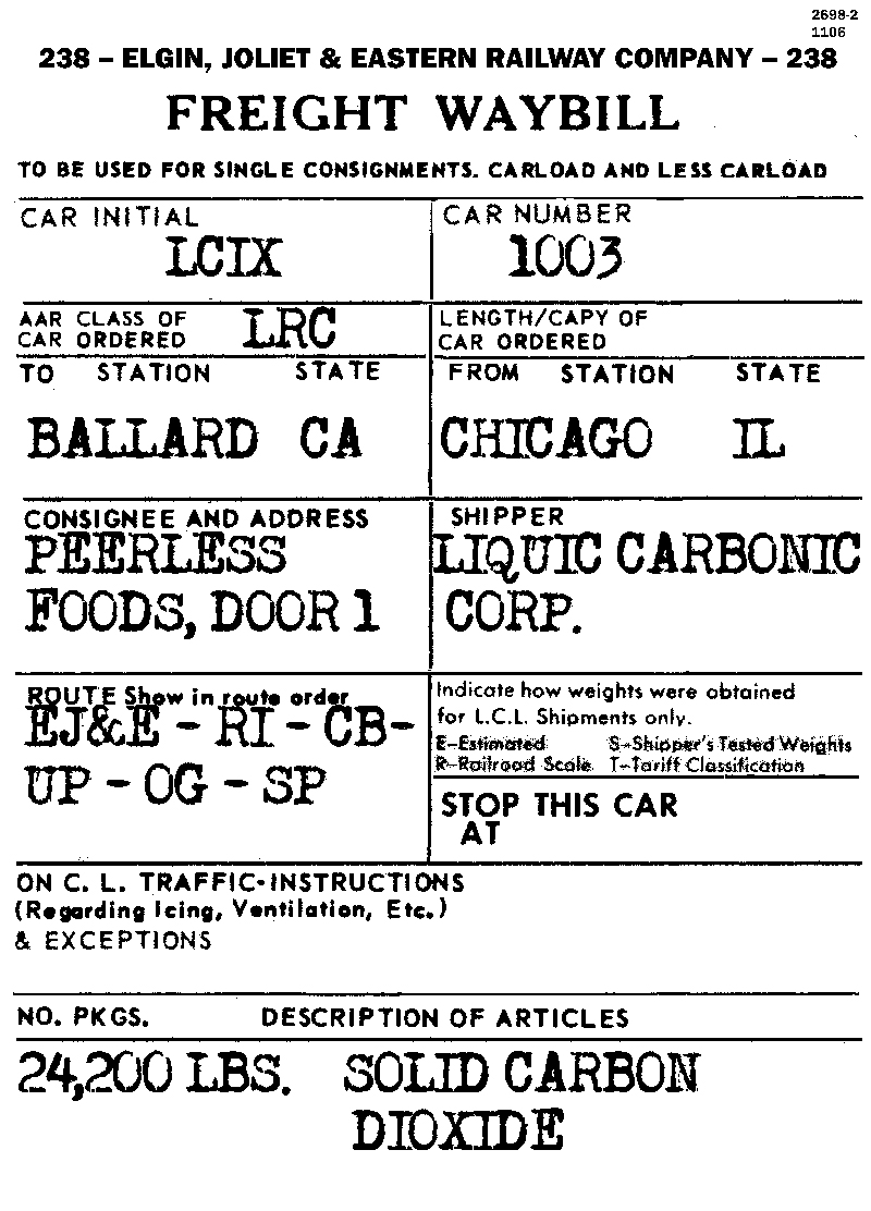
I researched the operations of Liquid Carbonic to find out where they had plants around the country to manufacture dry ice. Their real focus was originally on “carbonic acid,” which is carbon dioxide in water, supplied under pressure to get more CO2 into solution, and used to make carbonated water for soda fountains (for a nice summary of their role here, see this: https://www.drugstoremuseum.com/soda-fountain/liquid-carbonic-co/ ). In fact, Liquid Carbonic manufactured complete soda fountains for years. When they started producing dry ice, they took advantage of their name recognition, and called it “carbonic ice,” as is lettered on this car. Later they got into the supply of many industrial gasses. Their main plant was in Chicago, so I decided to have my on-line shipments arrive from there. Here is one of the waybills I use.
This was a fun project for me, bringing an ancient Varney cardstock freight car up to a level that I could use it on my layout. There are only a few cars this classical in my freight car fleet, but I am glad to have them and, what’s more, to operate them.
Tony Thompson
The kit models a dry-ice car owned by the Liquid Carbonic Corporation of Chicago. These were heavily insulated for their very cold cargo, and most cars for this service had distinctive details. The Varney car was intended to represent one of 11 cars in a 1934-built car series, numbered 1000–1010. The cars were originally classified in AAR Class RC, for carbon-dioxide refrigerators, but this type of car was later moved into AAR Class L, for special car types, specifically Class LRC, for carbon-dioxide cars. And by the way, all 11 cars of this series were still in service in 1953, the year I model. Here is an AC&F builder photo.
You can see the silver color of the car, including the roof, and the slight taper of the upper half of the car sides (also visible, of course, on the ends). The volume of insulation is indicated by the fact that although the car was 44 feet long inside, it only had a cubic capacity of 703 cubic feet. Calling it a “refrigerator” is a bit of a misnomer, of course, since it only carried the refrigerant as a cargo, but it is certainly within the general characteristics of insulated house cars, like reefers and insulated box cars.
I have seen a number of these Varney models at swap meets over the years, often badly assembled or dented from rough handling, and not attractive to try and rescue. The car sides and ends are foil-covered cardstock, and do dent easily. But eventually I found one in good shape, and decided to give it a go. The overly heavy grab irons and the sill steps made from staples were removed, along with the dummy couplers on the car. Here is the state of the car at that point.
The car is missing the side ladder below the door, and the foil on one end has separated from the underlying cardstock (easily re-glued). You may note that Varney did not deign to reproduce the side taper, an omission I can live with. The lettering scheme is a later one than the scheme in the builder photo shown above.
I needed to clean up and repair the roof, and of course add a running board. I also added wire grab irons and Tuttle sill steps, and a ladder under the side door, with an accompanying sill step under that ladder. The as-built kit is close to weightless, so I glued some sheet lead to the floor on either side of the center sill. I also added end lettering, as well as reweigh and repack paint patches (the black rectangles below) and lettering from Sunshine data sets.
I researched the operations of Liquid Carbonic to find out where they had plants around the country to manufacture dry ice. Their real focus was originally on “carbonic acid,” which is carbon dioxide in water, supplied under pressure to get more CO2 into solution, and used to make carbonated water for soda fountains (for a nice summary of their role here, see this: https://www.drugstoremuseum.com/soda-fountain/liquid-carbonic-co/ ). In fact, Liquid Carbonic manufactured complete soda fountains for years. When they started producing dry ice, they took advantage of their name recognition, and called it “carbonic ice,” as is lettered on this car. Later they got into the supply of many industrial gasses. Their main plant was in Chicago, so I decided to have my on-line shipments arrive from there. Here is one of the waybills I use.
This was a fun project for me, bringing an ancient Varney cardstock freight car up to a level that I could use it on my layout. There are only a few cars this classical in my freight car fleet, but I am glad to have them and, what’s more, to operate them.
Tony Thompson
Wednesday, September 20, 2017
Modeling freight traffic, Coast Line, Part 13
In a previous post, I showed elements of Southern Pacific’s “Condensed Perishable, Merchandise and Manifest Train
Schedule No. 15,” published for Pacific Lines, which went into effect on March 5, 1954, thus very close to my 1953 modeling era. The post is at: http://modelingthesp.blogspot.com/2012/01/modeling-freight-traffic-coast-line.html . That post covered mainline freight trains, except perishable schedules, and I discussed the complexities of perishable traffic in a separate post, which can be found at: http://modelingthesp.blogspot.com/2011/01/modeling-freight-traffic-coast-line_17.html .
It is interesting to compare those 1954 listings with later schedules, for additional insight into some of the trains. The Southern Pacific Historical & Technical Society magazine, Trainline, recently published the entirety of Timetable No. 17, of June 23, 1957. (It is in the Trainline issue for Spring 2017.) Here is the header for that document (you can click to enlarge):
These schedules in that period were on a single large sheet of paper, about 17 x 22 inches. The Coast Route part was only a small section of the total.
The Coast schedule itself, like those for each Route, was presented in ordinary timetable fashion, giving the times at only a few principal points, though in fact these listed times were only “guidelines,” not rigorously timed schedules.
The real meat of this information is in the so-called Notes, at one side of the schedule, which describe actual train goals and operation for each Route. These notes are the core of what we want to learn as modelers of prototype operation. Much of this material is like the Notes for Schedule 15, on which I have commented in that previous post (see paragraph at top for link). Here are the Schedule 17 Notes.
The interesting point here is to compare this information from Schedule 17, to that in the Schedule 15 I showed in that earlier post (see link in first paragraph, above). Nearly all the trains remain the same, with the same symbols, though the MM and MX of Schedule 15 have gone, and now the “Overnight” has a companion “Advance Overnight” as well.
More interesting, perhaps, is that the schedules of some trains are significantly speeded up. The general or manifest trains were the LA (Los Angeles Manifest) and the Sunset East or SSE eastward, and the GGM (Golden Gate Manifest) and SF (San Francisco Manifest) westward. The LA has been greatly speeded up in Schedule 17, compared to No. 15, and now is described as handling auto parts and automobiles out of Gemco in Van Nuys. But the other train Notes remain much the same, though departing and arriving in entirely different parts of the day.
The more important point is that in either schedule, there were trains that took many hours to traverse the route between Los Angeles and San Francisco. The Daylight could cover this route in a little under 10 hours, but there were freights scheduled to take fully 30 hours. There is an image in the popular imagination of the “red ball” freight, thundering over the road with vital cargo, hitting every station with split-second precision. On the Coast Route, the two Coast Merchandise trains, CME and CMW, perhaps fit this description; these were the trains nicknamed “Overnights.” But the manifests on the Coast Route were practically the opposite.
Back in 1953, all four manifests (LA, SSE, GGM and SF) had very long schedules, and each had at least one intermediate point where the train was scheduled to be for hours. For example, for the SSE and GGM, it was 5 to 8 hours at San Luis Obispo; for the LA, 4 hours at San Jose and 2 hours at Watsonville Junction. All four trains are faster in 1957’s Schedule 17, though only the LA is significantly faster.
Of course these station times were for switching and re-blocking the train, perhaps setting out some cars and collecting blocks of others. At San Luis Obispo and Santa Barbara, and sometimes also at other points, power and cabooses would be changed and crews changed. But the point is, these were not “hot” trains in schedule terms.
I have described all these freights in previous posts, based on the timetable instead of the Manifest Freight Schedule. For example, this one: http://modelingthesp.blogspot.com/2011/01/modeling-freight-traffic-coast-line.html . This is the kind of information I like to have in designing operating patterns, even though I don’t directly model the change in train numbers at San Luis Obispo. Anyone researching comparable mainline freight operations might likewise find it essential to try and understand actual freight schedules.
Tony Thompson
It is interesting to compare those 1954 listings with later schedules, for additional insight into some of the trains. The Southern Pacific Historical & Technical Society magazine, Trainline, recently published the entirety of Timetable No. 17, of June 23, 1957. (It is in the Trainline issue for Spring 2017.) Here is the header for that document (you can click to enlarge):
These schedules in that period were on a single large sheet of paper, about 17 x 22 inches. The Coast Route part was only a small section of the total.
The Coast schedule itself, like those for each Route, was presented in ordinary timetable fashion, giving the times at only a few principal points, though in fact these listed times were only “guidelines,” not rigorously timed schedules.
The real meat of this information is in the so-called Notes, at one side of the schedule, which describe actual train goals and operation for each Route. These notes are the core of what we want to learn as modelers of prototype operation. Much of this material is like the Notes for Schedule 15, on which I have commented in that previous post (see paragraph at top for link). Here are the Schedule 17 Notes.
The interesting point here is to compare this information from Schedule 17, to that in the Schedule 15 I showed in that earlier post (see link in first paragraph, above). Nearly all the trains remain the same, with the same symbols, though the MM and MX of Schedule 15 have gone, and now the “Overnight” has a companion “Advance Overnight” as well.
More interesting, perhaps, is that the schedules of some trains are significantly speeded up. The general or manifest trains were the LA (Los Angeles Manifest) and the Sunset East or SSE eastward, and the GGM (Golden Gate Manifest) and SF (San Francisco Manifest) westward. The LA has been greatly speeded up in Schedule 17, compared to No. 15, and now is described as handling auto parts and automobiles out of Gemco in Van Nuys. But the other train Notes remain much the same, though departing and arriving in entirely different parts of the day.
The more important point is that in either schedule, there were trains that took many hours to traverse the route between Los Angeles and San Francisco. The Daylight could cover this route in a little under 10 hours, but there were freights scheduled to take fully 30 hours. There is an image in the popular imagination of the “red ball” freight, thundering over the road with vital cargo, hitting every station with split-second precision. On the Coast Route, the two Coast Merchandise trains, CME and CMW, perhaps fit this description; these were the trains nicknamed “Overnights.” But the manifests on the Coast Route were practically the opposite.
Back in 1953, all four manifests (LA, SSE, GGM and SF) had very long schedules, and each had at least one intermediate point where the train was scheduled to be for hours. For example, for the SSE and GGM, it was 5 to 8 hours at San Luis Obispo; for the LA, 4 hours at San Jose and 2 hours at Watsonville Junction. All four trains are faster in 1957’s Schedule 17, though only the LA is significantly faster.
Of course these station times were for switching and re-blocking the train, perhaps setting out some cars and collecting blocks of others. At San Luis Obispo and Santa Barbara, and sometimes also at other points, power and cabooses would be changed and crews changed. But the point is, these were not “hot” trains in schedule terms.
I have described all these freights in previous posts, based on the timetable instead of the Manifest Freight Schedule. For example, this one: http://modelingthesp.blogspot.com/2011/01/modeling-freight-traffic-coast-line.html . This is the kind of information I like to have in designing operating patterns, even though I don’t directly model the change in train numbers at San Luis Obispo. Anyone researching comparable mainline freight operations might likewise find it essential to try and understand actual freight schedules.
Tony Thompson
Sunday, September 17, 2017
VanRail 2017
For those who don’t know, VanRail is an operating weekend held in Vancouver, British Columbia in odd-numbered years. It is a wonderful event, with full Canadian hospitality, fine layouts, and accomplished layout owners. All in all, a real delight to attend, as I did this year on September 8 through 10.
There was a pre-VanRail session on September 7 at Al Frasch’s excellent N-scale BNSF layout on Whidbey Island, Washington, which I had very much looked forward to. I had met Al when he operated on my layout last spring during our BayRails event, and he and I had talked about a variety of waybill and freight car routing topics. The most striking thing to me about Al’s layout was how very “industrial” his industries looked. I know, that sounds a little redundant, but I was struck by the good looks of industry after industry. I did photograph a lot of them, but will only show one instance here, Skagit Bulb Company (flower bulbs). I like that box cars are spotted inside the building, yet the reporting marks are visible outside, a “just right” design.
I really like some of Al’s approaches to informing crews about how to spot cars at industries, and will be writing a future post about both Al’s method, and how I want to implement something similar on my own layout.
The first Vancouver layout I operated on was Greg Madsen’s freelanced HO scale Spokane and British Columbia Railway, and as it happened, Al Frasch was on the crew. Here he is, bringing a train into Grand Forks yard (where I was working as yardmaster at the time). Behind him is Doug Lee, the third operator that day.
I had communicated with Greg over the years about freight car forwarding, and was intrigued to see the system he is developing for this layout.
On Saturday, I had the genuine privilege to operate on Scott Calvert’s layout, the Canadian Pacific Boundary Sub in HO scale. My assignment was working at Nelson yard. Though much remains to be built on this layout, it is already strikingly good, with a very strong design concept and fine implementation so far. The photo below shows the trackage at Castlegar as it now stands. I regret not getting a better photo at Nelson, where I really enjoyed the challenge of switching the west end of the yard.
I wrapped up the weekend at Brian Morgan’s interesting N-scale layout, the Great Northern Seattle Terminal. I really liked his industries and switching assignments (all the operators essentially have switch jobs). One example of the well-thought-out design is this flour mill, a very large industry with five tracks in all, three running deep behind the rows of black tanks (that’s my switcher in the foreground). Obviously one cannot see what is back in there at the mill.
But Brian provided a very helpful laminated map, with car numbers written on it, as shown below. Note also the small “sticky dots” for those who would like to tag cars with original positions, so the ones not being pulled can be spotted back where they came from. I found I could use just the map to do all that, but it was nice to have two options.
At the end of the session, Brian used his tripod to take a picture of the three operators and himself, as you see below. From left, we were Seth Neumann, me, Travers Stavac, and Brian.
This was a great weekend. I really enjoyed the beautiful city of Vancouver and all the layouts, and was very pleased with the cordial hospitality of our Canadian hosts. I hope to attend this event in future years.
Tony Thompson
There was a pre-VanRail session on September 7 at Al Frasch’s excellent N-scale BNSF layout on Whidbey Island, Washington, which I had very much looked forward to. I had met Al when he operated on my layout last spring during our BayRails event, and he and I had talked about a variety of waybill and freight car routing topics. The most striking thing to me about Al’s layout was how very “industrial” his industries looked. I know, that sounds a little redundant, but I was struck by the good looks of industry after industry. I did photograph a lot of them, but will only show one instance here, Skagit Bulb Company (flower bulbs). I like that box cars are spotted inside the building, yet the reporting marks are visible outside, a “just right” design.
I really like some of Al’s approaches to informing crews about how to spot cars at industries, and will be writing a future post about both Al’s method, and how I want to implement something similar on my own layout.
The first Vancouver layout I operated on was Greg Madsen’s freelanced HO scale Spokane and British Columbia Railway, and as it happened, Al Frasch was on the crew. Here he is, bringing a train into Grand Forks yard (where I was working as yardmaster at the time). Behind him is Doug Lee, the third operator that day.
I had communicated with Greg over the years about freight car forwarding, and was intrigued to see the system he is developing for this layout.
On Saturday, I had the genuine privilege to operate on Scott Calvert’s layout, the Canadian Pacific Boundary Sub in HO scale. My assignment was working at Nelson yard. Though much remains to be built on this layout, it is already strikingly good, with a very strong design concept and fine implementation so far. The photo below shows the trackage at Castlegar as it now stands. I regret not getting a better photo at Nelson, where I really enjoyed the challenge of switching the west end of the yard.
I wrapped up the weekend at Brian Morgan’s interesting N-scale layout, the Great Northern Seattle Terminal. I really liked his industries and switching assignments (all the operators essentially have switch jobs). One example of the well-thought-out design is this flour mill, a very large industry with five tracks in all, three running deep behind the rows of black tanks (that’s my switcher in the foreground). Obviously one cannot see what is back in there at the mill.
But Brian provided a very helpful laminated map, with car numbers written on it, as shown below. Note also the small “sticky dots” for those who would like to tag cars with original positions, so the ones not being pulled can be spotted back where they came from. I found I could use just the map to do all that, but it was nice to have two options.
At the end of the session, Brian used his tripod to take a picture of the three operators and himself, as you see below. From left, we were Seth Neumann, me, Travers Stavac, and Brian.
This was a great weekend. I really enjoyed the beautiful city of Vancouver and all the layouts, and was very pleased with the cordial hospitality of our Canadian hosts. I hope to attend this event in future years.
Tony Thompson
Thursday, September 14, 2017
Building the Owl Mountain flat car
The announcement of this new HO scale kit for a “Harriman” flat car, very numerous in the Southern Pacific freight car fleet, was posted recently (you can read my introduction to the kit at: http://modelingthesp.blogspot.com/2017/08/new-flat-car-kit-from-owl-mountain.html ). Having said all those introductory things, I now want to describe building the kit.
To begin, I want to repeat my general approach in describing kit building. When steps are simple and straightforward, there is certainly no need for me even to mention them. Only if something in the instructions is hard to understand, or if I deviate from or work beyond the instructions, do I see any need for comments. So this post does not constitute a step-by-step kit build, just a kind of “highlights as I saw them.”
Step 1 in the instructions is to prepare the deck. I like styrene flat car decks, because they are much easier to distress and age in a convincing way, and there is no enormous, out-of-scale grain of “real wood” to hide. I cut some gouges and scrapes with the corners of an X-acto chisel blade, then roughened the entire surface with 60-grit abrasive paper. Here is how it looked; you may wish to click on the image to enlarge it.
Although by the time I model, 1953, cars like this were decades old, the deck probably would not be as old. Flat car decks took a real beating in service, and were replaced whenever sufficiently decrepit. For a car like this, one could model anything from nearly new, to falling apart, or anything in between, and still be reasonably “correct.”
After Step 1, assembling the basic parts (instruction Steps 2 through 9) is very simple and straightforward. The first time I had any challenge was in Step 10, attaching the beautiful little brass castings of the distinctive Harriman roping staples. The pins that are supposed to fit into holes in the side sill are tapered, not cylindrical, and it took some judicious filing of those pins to get them to fit. Alternatively, a person could simply drill the reception holes a little larger. Do check that the parts fit flush against the side sill, and nestle into the side sill notch at the attachment location.
Note the center and end sills are gray on my model. I received a gray test shot of this sprue but the production kits have this sprue in boxcar red.
The next step might make some modelers quail, bending your own grab irons. But don’t feel that way. The kit supplies a little bending jig for this purpose, and it works fine. If you have any problems installing the grabs, you might wish to drill the holes a little larger; and if inserting small wires into small holes in a dark material is challenging, use a stronger light. Also, the kit instructions specify the height of the grab iron to be the thickness of an X-act blade, and you should recognize that on the side grabs, this means the height outside the stake pocket. Otherwise, of course, an HO scale brakeman couldn’t use the grab iron.
With all grab irons installed, I went ahead with the brake system details, steps 12 to 17. These went smoothly, and upon completion, here is the underbody appearance. The white styrene is the 0.010-inch shim.
After this point, I only need to add coupler box lids and the very nice sill steps, before doing the painting. Simply putting the car on its back, as you see above, one automatically “masks” the top of the deck, and can quickly airbrush boxcar red onto the underbody. I intend to make the deck boards look like SP’s typical untreated wood, suitably weathered from use. Certainly as late as 1960, SP definitely did not use creosoted wood for flat car decks. Pressure-treated wood, yes; creosoted, no.
Upon completion of painting the underbody and sides, I gave the sides a coat of clear gloss for decal application. The kit instructions contain an excellent lettering diagram, particularly helpful with a car like this one, with most lettering quite small. As a person who enjoys applying decals, I found this straightforward, but some may find it a little fussy. Still, it all works, and looks good. The decals were protected with clear flat, then the car was weathered with my usual method using acrylic tube paints, a mix of primarily Neutral Gray, Black, and a little Burnt Umber. This is intended to represent a well-used deck (for more on flat car decks, you may wish to read this post: http://modelingthesp.blogspot.com/2011/05/weathering-flat-car-decks.html ). This Owl Mountain deck was made more gray and less brown than a newer deck would be.
Here is the completed kit, with trucks and couplers installed, and the brake staff added in the final step (as the kit instructions recommend). I installed Reboxx wheels in the kit trucks. You can see I numbered the car as SP 43419, Class F-50-12.
On balance, I think this is a great kit. It goes together very well, and the accomplished design becomes evident as you assemble the parts. And as I stated in my introductory post, it is a much-needed kit, particularly for SP modelers, but also for anyone modeling up to the end of the Transition Era, with lumber loads. (Owl Mountain has announced a load kit just for this model.) Carrying those loads, and many other typical flat car loads, these cars went everywhere in the country. You do need this car!
Tony Thompson
To begin, I want to repeat my general approach in describing kit building. When steps are simple and straightforward, there is certainly no need for me even to mention them. Only if something in the instructions is hard to understand, or if I deviate from or work beyond the instructions, do I see any need for comments. So this post does not constitute a step-by-step kit build, just a kind of “highlights as I saw them.”
Step 1 in the instructions is to prepare the deck. I like styrene flat car decks, because they are much easier to distress and age in a convincing way, and there is no enormous, out-of-scale grain of “real wood” to hide. I cut some gouges and scrapes with the corners of an X-acto chisel blade, then roughened the entire surface with 60-grit abrasive paper. Here is how it looked; you may wish to click on the image to enlarge it.
Although by the time I model, 1953, cars like this were decades old, the deck probably would not be as old. Flat car decks took a real beating in service, and were replaced whenever sufficiently decrepit. For a car like this, one could model anything from nearly new, to falling apart, or anything in between, and still be reasonably “correct.”
After Step 1, assembling the basic parts (instruction Steps 2 through 9) is very simple and straightforward. The first time I had any challenge was in Step 10, attaching the beautiful little brass castings of the distinctive Harriman roping staples. The pins that are supposed to fit into holes in the side sill are tapered, not cylindrical, and it took some judicious filing of those pins to get them to fit. Alternatively, a person could simply drill the reception holes a little larger. Do check that the parts fit flush against the side sill, and nestle into the side sill notch at the attachment location.
Note the center and end sills are gray on my model. I received a gray test shot of this sprue but the production kits have this sprue in boxcar red.
The next step might make some modelers quail, bending your own grab irons. But don’t feel that way. The kit supplies a little bending jig for this purpose, and it works fine. If you have any problems installing the grabs, you might wish to drill the holes a little larger; and if inserting small wires into small holes in a dark material is challenging, use a stronger light. Also, the kit instructions specify the height of the grab iron to be the thickness of an X-act blade, and you should recognize that on the side grabs, this means the height outside the stake pocket. Otherwise, of course, an HO scale brakeman couldn’t use the grab iron.
With all grab irons installed, I went ahead with the brake system details, steps 12 to 17. These went smoothly, and upon completion, here is the underbody appearance. The white styrene is the 0.010-inch shim.
After this point, I only need to add coupler box lids and the very nice sill steps, before doing the painting. Simply putting the car on its back, as you see above, one automatically “masks” the top of the deck, and can quickly airbrush boxcar red onto the underbody. I intend to make the deck boards look like SP’s typical untreated wood, suitably weathered from use. Certainly as late as 1960, SP definitely did not use creosoted wood for flat car decks. Pressure-treated wood, yes; creosoted, no.
Upon completion of painting the underbody and sides, I gave the sides a coat of clear gloss for decal application. The kit instructions contain an excellent lettering diagram, particularly helpful with a car like this one, with most lettering quite small. As a person who enjoys applying decals, I found this straightforward, but some may find it a little fussy. Still, it all works, and looks good. The decals were protected with clear flat, then the car was weathered with my usual method using acrylic tube paints, a mix of primarily Neutral Gray, Black, and a little Burnt Umber. This is intended to represent a well-used deck (for more on flat car decks, you may wish to read this post: http://modelingthesp.blogspot.com/2011/05/weathering-flat-car-decks.html ). This Owl Mountain deck was made more gray and less brown than a newer deck would be.
Here is the completed kit, with trucks and couplers installed, and the brake staff added in the final step (as the kit instructions recommend). I installed Reboxx wheels in the kit trucks. You can see I numbered the car as SP 43419, Class F-50-12.
On balance, I think this is a great kit. It goes together very well, and the accomplished design becomes evident as you assemble the parts. And as I stated in my introductory post, it is a much-needed kit, particularly for SP modelers, but also for anyone modeling up to the end of the Transition Era, with lumber loads. (Owl Mountain has announced a load kit just for this model.) Carrying those loads, and many other typical flat car loads, these cars went everywhere in the country. You do need this car!
Tony Thompson
Monday, September 11, 2017
Weight of loads, Part 2
Awhile back, I showed the calculations I have done for some of my open car loads, including one load of steel bar that would be too heavy for a 50-ton car, but would have to move in a 70-ton car (that post can be seen at: http://modelingthesp.blogspot.com/2016/11/open-car-loads-weight.html ). In the present post, I want to continue this topic.
Years ago, I bought some cast white metal models of steel coils. These are the kind of coils that in later years moved in specially equipped gondolas, and later still in purpose-built coil cars. But in the early 1950s, when I model, they were often simply loaded into gondolas, either in wood cradles built for each coil, or laid down on their sides. I don’t really remember the source of these coils, though Red Ball sticks in my mind. The coils look like this, before any painting:
I will paint the coil steel gray (a bluish-gray color) and paint the strapping black.
Just to illustrate, here are the dimensions of one of these coils in scale feet and inches. The outer diameter is 6' 3" and the inner diameter is 3' 7", with a height of the coil at 2' 9". One can readily calculate the gross surface area of the entire top of the cylinder, and subtract the inner diameter or hole, to get the net area of the circular coil. Then multiplying by the height gives the volume in cubic feet, which I obtain as 56.6 cubic feet. Since the density of steel is 490 pounds per cubic foot, the weight of one of these coils would be 27,750 pounds. I have three of the coils, which looks a little sparse in a 40-foot gondola, but in fact three of them would weigh 83,250 pounds, quite a respectable load for a 50-ton car. Here are those three coils in a gondola.
In the foreground you may note one of SP’s standard speed signs. I have discussed those signs in a prior post, and shown this specific sign (see that post at: http://modelingthesp.blogspot.com/2014/03/speed-signs.html ). As the milepost on the phone pole in the background indicates, this is mile 270 on the Coast Route. In another previous post, I described the SP standards for such signs, and showed this one in place (the post can be found at: http://modelingthesp.blogspot.com/2014/03/milepost-markers.html ).
Another example is one of the excellent Duha loads from the Czech Republic (these have been imported for several years now by JWD Premium Products in Maine). It appears to be represented as steel plates, about 2 scale inches thick, with five longer plates and two shorter plates, the latter also a little narrower. What appear to be 2-inch plates may be intended as pairs of 1-inch plates, or even packs of thinner sheet. But for calculating density, it doesn’t much matter. Here is its appearance.
The sag in the upper stack does suggest sheet rather than 2-inch plate.
One can readily measure the plate (or sheet stack) thickness, then the plan dimensions, all in inches, multiply by 87 to obtain HO scale dimensions, then multiply dimensions together to get the volume of each plate in scale cubic inches. Then using the handbook density of steel, 0.2904 pounds per cubic inch. one arrives at the total weight of each plate. The long plates weigh 21,000 pounds and the short plates about 12,500 pounds. This makes the total weight of this load about 125,000 pounds. This is just above the typical load limit of SP 40-foot gondolas, which was about 119,000 pounds. Thus such a plate load should either be placed in 70-ton gondolas, or else on 50-ton flat cars, which usually have a load limit more like 130,000 pounds.
Most loads for open-top cars would not have weight issues, but when masses of steel are depicted, it seems to me worth checking what the actual weight of such a load might be. When the load is too heavy for some cars, I simply restrict use of that load to appropriate cars. But this Duha load is a good illustration of an obvious point: since it’s a great-looking load, many modelers will be happy to put it in whatever car they have handy.
Tony Thompson
Years ago, I bought some cast white metal models of steel coils. These are the kind of coils that in later years moved in specially equipped gondolas, and later still in purpose-built coil cars. But in the early 1950s, when I model, they were often simply loaded into gondolas, either in wood cradles built for each coil, or laid down on their sides. I don’t really remember the source of these coils, though Red Ball sticks in my mind. The coils look like this, before any painting:
I will paint the coil steel gray (a bluish-gray color) and paint the strapping black.
Just to illustrate, here are the dimensions of one of these coils in scale feet and inches. The outer diameter is 6' 3" and the inner diameter is 3' 7", with a height of the coil at 2' 9". One can readily calculate the gross surface area of the entire top of the cylinder, and subtract the inner diameter or hole, to get the net area of the circular coil. Then multiplying by the height gives the volume in cubic feet, which I obtain as 56.6 cubic feet. Since the density of steel is 490 pounds per cubic foot, the weight of one of these coils would be 27,750 pounds. I have three of the coils, which looks a little sparse in a 40-foot gondola, but in fact three of them would weigh 83,250 pounds, quite a respectable load for a 50-ton car. Here are those three coils in a gondola.
In the foreground you may note one of SP’s standard speed signs. I have discussed those signs in a prior post, and shown this specific sign (see that post at: http://modelingthesp.blogspot.com/2014/03/speed-signs.html ). As the milepost on the phone pole in the background indicates, this is mile 270 on the Coast Route. In another previous post, I described the SP standards for such signs, and showed this one in place (the post can be found at: http://modelingthesp.blogspot.com/2014/03/milepost-markers.html ).
Another example is one of the excellent Duha loads from the Czech Republic (these have been imported for several years now by JWD Premium Products in Maine). It appears to be represented as steel plates, about 2 scale inches thick, with five longer plates and two shorter plates, the latter also a little narrower. What appear to be 2-inch plates may be intended as pairs of 1-inch plates, or even packs of thinner sheet. But for calculating density, it doesn’t much matter. Here is its appearance.
The sag in the upper stack does suggest sheet rather than 2-inch plate.
One can readily measure the plate (or sheet stack) thickness, then the plan dimensions, all in inches, multiply by 87 to obtain HO scale dimensions, then multiply dimensions together to get the volume of each plate in scale cubic inches. Then using the handbook density of steel, 0.2904 pounds per cubic inch. one arrives at the total weight of each plate. The long plates weigh 21,000 pounds and the short plates about 12,500 pounds. This makes the total weight of this load about 125,000 pounds. This is just above the typical load limit of SP 40-foot gondolas, which was about 119,000 pounds. Thus such a plate load should either be placed in 70-ton gondolas, or else on 50-ton flat cars, which usually have a load limit more like 130,000 pounds.
Most loads for open-top cars would not have weight issues, but when masses of steel are depicted, it seems to me worth checking what the actual weight of such a load might be. When the load is too heavy for some cars, I simply restrict use of that load to appropriate cars. But this Duha load is a good illustration of an obvious point: since it’s a great-looking load, many modelers will be happy to put it in whatever car they have handy.
Tony Thompson
Subscribe to:
Posts (Atom)