Sunday, May 19, 2013

A new SP bridge for Shumala

The bridge which carries my SP branch line over Chamisal Road in Shumala needs to be replaced. I originally built this bridge as a through girder due to tight clearances underneath, but I made it far too “deep” (height of the plate girder, relative to length). I will explain in a moment how one knows how deep such a girder should be, but here is the old bridge, when it served the Lompoc & Cuyama short line (for which the diesel is lettered). You can click to enlarge.


     The span of this bridge is only 25 feet, about the minimum for which the prototype would build a girder bridge instead of a bridge of simple beams across the gap. Again, I am stating prototype design information. I rely on Paul Mallery’s outstanding book, Bridge and Trestle Handbook, for this kind of background.
     [I will digress briefly about this title. The book was first published by Simmons-Boardman in 1958, in hard covers. A revised edition in paper covers was published in 1976 by Boynton and Associates, and a third edition in spiral-bound form somewhat later. The currently available fourth edition is published by Carstens, and has been expanded with the addition of many photographs and some new drawings; it first came out in 1992.]
     Here is my (well worn) copy of the second or Revised Edition. The fourth edition contains the same information and would work equally well, but pagination changed, so I will refer to my second edition for specific sections or pages.


     I used this edition for this project, especially Chapter 9 on plate-girder bridges. It contains a table of typical length and height of girders, which appear to range between 7 and 9 times longer than they are high, in other words, a height-to-length ratio between 7:1 and 9:1. For a 25-foot span, that means a height of about three feet on the side girders. The table also shows that a bridge of the size of my space would typically have three or four stiffening ribs (the one in the photo at top has three). Lastly, you can see in the photo above that I built the original bridge with rounded upper girder corners, but SP practice was predominantly square-corner girders.
     I should mention, for anyone with a file of old Model Railroader issues (or the DVD collection), that Harold Russell published an excellent six-part series on railroad bridges in 1988, appearing in all issues from July to December (inclusive). This provides, in some cases, more detail than Mallery’s book and is well worth a look if you need details about bridges.
      My original bridge, top photo in this post, was built as an open-deck design, that is, with the structural steel underneath the track visible from above, although on the SP it was pretty common for such bridges to have ballasted decks. I decided to follow SP practice this time and model a ballasted deck. That meant I simply had to build up two girders, and nowadays, with Archer rivets available for such work, it is not the challenging problem it once was.
     For this project, I used Archer HO set 88025, which has three spacings of scale 7/8-inch rivet heads (I mostly used the intermediate spacing). I should mention that Archer does catalog a set called “Bridge Rivets,” HO set 88052, but they are pretty widely spaced compared to any through girder bridges I have seen in person or photographs. They may be useful for other bridge types. You can see the range of Archer rivet sets at this link; scroll down to HO scale: http://www.archertransfers.com/SurfaceDetailsMain.html .
     I began with some 0.030-inch sheet styrene. Mallery shows that all the stiffening angles which are attached to a girder like this are six scale inches wide, so for simplicity I used Evergreen styrene strip, scale 1 x 6-inch. These are quickly applied with styrene cement. Here is how the girders looked after laying out the stiffener locations with pencil and applying the top and bottom strips of 1 x 6. The small machinist’s square is essential to keep everything perpendicular as it should be.


I then cut to length all the bases of the stiffener members (since they are angles on the finished bridge) and installed those too. At this point it seemed best to get the first set of rivets onto the girders, so I then applied the Archer rivets to their locations on the girder surface.


The upper girder in the photo has all its surface rivets, the lower one is partly done. A few of the crosspieces are not perfectly perpendicular, but this can be disguised when the standing leg of the angle is applied.
     I might mention that applying black rivets to white styrene is greatly easier than applying them to, say, black styrene. I had the latter experience with my circumferential rivets on a (black) Athearn tank car. (You can read that story at: http://modelingthesp.blogspot.com/2012/10/modeling-sp-tank-cars-4-circumferential.html .) Once all surface rivets were in place, I added a protective overspray of Testor’s Dullcote, since the rivets can be knocked off the decals otherwise.
     Next was a test fit to verify that the girders do fit into the distance between the bridge abutments, since further work would make length adjustments complicated. I then applied styrene strip entirely around the girders, to make the outside flanges. I used HO scale 1 x 10-inch Evergreen strip. These flanges should have double rivet rows, which attach the angle stiffeners inside of them, on each side of the plate.
    Next I used scale 1 x 4-inch styrene strip to make the standing leg of each of the side stiffeners. Here is how the girders looked at this point:


    My next step will be to apply Archer rivets along the outside of all the outside flanges. Then the girders will be ready for painting, with black being a common color for SP bridges. They did paint some bridges aluminum, usually ones crossing significant highways, so I think this small bridge is a better candidate for black. But I will proceed with that part of the work in a following post.
Tony Thompson

Thursday, May 16, 2013

Modeling meat reefers –– Part 5

In my previous post on my meat reefer project, which is available at: http://modelingthesp.blogspot.com/2013/04/modeling-meat-reefers-part-4.html , I described the completion of painting, and the application of dry transfer lettering to the four cars of this project. In this final post, I show all the cars.
     But it is worth mentioning, for those with an inordinate fear of dry transfers (I’m just joking), that some of the lettering for these same reefers is also available in decal form from Jerry Glow. You can see his catalog at: http://home.comcast.net/~jerryglow/decals/full.html . You can scroll down the alphabetical listing to Armour, Swift, and Wilson. But I will repeat my comment from the previous post: if you proceed with care, dry transfers work every bit as well as decals — they are just applied differently.
     The Cudahy and 1948 Swift cars already lettered were shown in the previous post, though in an unweathered condition. Here is the finished Cudahy car, spotted for unloading at the Peerless Foods wholesale grocery warehouse in Ballard, on my layout.


Also shown at its normal destination, Peerless Foods, is the 1948-scheme Swift car.


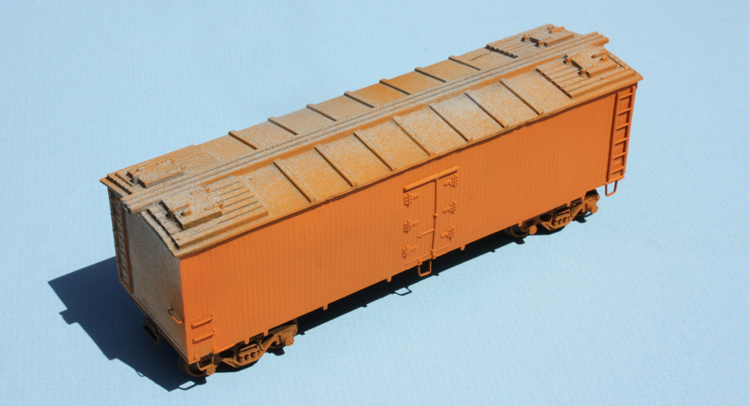
    Previously I didn’t show the orange Wilson car, the sides of which I airbrushed Floquil Daylight Orange as a reasonable light orange, so here it is. The temporary trucks are a roller-bearing type, among my “spray booth” trucks.


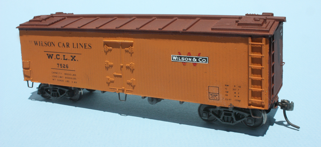
     The next step was the application of boxcar red to the roof and ends, then arranging the lettering with the Clover House dry transfer set identified earlier, no. 9416-01. I applied my usual Kadee no. 58 couplers and, for this car, a pair of Tahoe Model Works Buckeye trucks, which have the sideframe shape visible in many photos of Wilson cars, and correctly have spring planks. These are TMW part no. 106. In this photo, the car isn’t yet weathered; note the transverse reservoir mounting, typical of Wilson reefers.


     Lastly, my model of an Armour car is a repainted Atlas reefer, which was manufactured with an unusual four-hinge side door instead of the more common six-hinge door. The four-hinge door might have been chosen so that the doors could be made to operate. As I have neither need nor interest in operating reefer side doors, I glued them closed and shaved off the oversize hinges.
     As far as I know, Armour did not have any four-hinge-door cars, so I simply added two Grandt Line reefer hinges (Grandt part 5168) to each door to make up the difference. The Grandt parts are a good match to the style of the Atlas hinges, and are molded in dark gray, so I simply sprayed them with flat black before installing on the reefer body.
     The prototype Armour cars appear to have continued to receive black side hardware (door hinges and latch bars, grab irons, and sill steps) after most other meat car owners had decided to paint the side hardware body color. I simply used a small brush to paint the various details black. The Atlas Vulcan trucks, though not well rendered, do resemble some trucks visible under Armour cars, so I chose to retain them on the model. And here is the car, fairly dirty to represent the appearance of many Armour cars in later years.


     This completes my little fleet of four new meat reefers, all of the typical 36- or 37-foot length, and visibly different from the many 41-foot produce reefers, PFE and otherwise, on my layout. As I said at the outset of this thread (see my post at: http://modelingthesp.blogspot.com/2011/02/modeling-meat-reefers.html ), I am one of many modelers waiting eagerly for the new Rapido meat cars (now delayed over two years), but in the meantime, I have these.
Tony Thompson

Sunday, May 12, 2013

A few words in praise of canopy glue

Some people reading this title will say “yeah, sure,” and doubtless others may say “what the heck is canopy glue?” For the latter folks, read on. But even if you know what it is, you may not appreciate all it can do.
     Canopy glue was developed, as the name suggests, for aircraft modelers. They have the challenge of gluing a foil “frame” onto a transparent plastic molding of an airplane canopy. The glue that’s best has these features: it doesn’t attack or craze plastic; it glues the dissimilar materials well (metal foil and plastic); it dries clear and glossy, so any excess outside the foil is minimally visible; and it remains flexible for any differences in expansion and contraction of the materials that are glued together.
     Some of these features turn out to be terrific for certain kinds of railroad modeling too. I have found canopy glue to be simply outstanding for gluing different materials together: metal to plastic, plastic to wood or cardstock, metal to wood, etc. (porous materials are no problem), just in terms of how well they adhere. And the “remains flexible” part is vital too. That’s why I use it exclusively for etched metal parts, like running boards or diesel grilles. In the many years since I first used it, I have never had one of these metal parts pop off its model, as many people have experienced with CA or other rigid adhesives. Some people have utilized canopy glue’s property of drying clear and glossy to make small model windows, but I personally have not found this to work very well.
     So where do you get this stuff? Usually it’s only in the model airplane section of your hobby shop – the railroad side of the shop often doesn’t seem to know about it. Craft and art stores sometimes have it too. And yes, you can order it on the internet, with shipping no problem because it’s water-based. Amazon is just one of many sites where it is available.
     Sometimes you will hear it said, “it’s just white glue.” In my opinion, that’s not even close to true, except that it’s a white color and is water-base. It is much tackier right away than any white glue I’ve used – helpful in assembling things – and is much stronger when fully dry. It sets up pretty strong in three hours and develops full strength in about 24 hours. There is an Elmer’s product called Tacky Glue, but it is definitely not the same as canopy glue, being distinctly less strong. Information I’ve found says that canopy glue contains a vinyl acetate polymer, but the same appears to be true for ordinary white glue. Maybe the quantity of the polymer varies.
     The source used to be Wilhold, a big glue company, and their product was named R/C-56 (for Radio/Control, obviously alluding to model airplanes). In the 1990s, Wilhold stopped making this glue. Today, there are at least two sources: one is Testor’s, the other is Pacer. (Pacer Technology sells canopy glue under the Pacer name and also under the Zap name.) Chatting with those who patronize the airplane section of hobby shops, my perception is that Pacer is regarded as much better. Here are both Pacer containers, with the Wilhold product in the center.


I think it is no accident that the Pacer version is called “Formula 560,” given that the product which introduced many to this glue was called R/C-56. In fact, Pacer’s code name for the product is PT-56.
     Here are two examples of how I use canopy glue, both being the potentially troublesome etched metal parts of some length. The F7-B unit has an etched grille, and the PFE reefer has an etched running board. Both were attached years ago with canopy glue, both have undergone a goodly range of temperature variation since, and neither has budged in the slightest.


     All I can say is, if you don’t already know and rely on this glue, you should give it a try. Use it for something where CA or other adhesives have let you down, and see if it isn’t better. And any time you wrinkle your brow deciding how to join two dissimilar materials, here is your answer.
Tony Thompson

Thursday, May 9, 2013

Upgrading old models -- Athearn reefers, Part 4

In previous posts, I described my goal in this project, to create reasonable models of two PFE classes, R-40-14 and R-40-20, which had W-corner post ends and thus are not readily modeled with the excellent InterMountain versions of either R-40-10 or R-40-23. I used Athearn reefer bodies, and simply replaced the ends with new ends from Westrail (see the post at: http://modelingthesp.blogspot.com/2013/05/upgrading-old-models-athearn-reefers.html ).
     Once the ends had been airbrushed boxcar red, I added the end lettering (I found this much more convenient on an end lying flat on the bench).


Then I assembled them to the bodies with model airplane canopy cement, adjusted any gaps with modeling putty, and did a final touchup with the boxcar red paint.
     A few words on paint schemes: I will describe my thinking for the two models in question, but hopefully these comments will illuminate the general topic of PFE paint schemes at particular eras.
     To start, it’s useful to recognize that PFE (like SFRD and to a lesser extent ART and FGE) directed empty cars, as they came west, arriving onto the parent railroads, UP and SP, to their own shops for inspection and (if necessary) repair. This essentially happened after every loaded trip of the PFE cars. This is an extreme difference from free-running cars like box cars or gondolas, which might wander from railroad to railroad for a year or more and never return to home rails. Thus PFE not only could readily undertake any upgrading campaigns for particular classes, and complete them in a matter of months, but could also repaint cars as that was needed, across the fleet.
     The overall pattern of PFE painting practice was described to me in a 1985 interview with Earl Hopkins. So you know who he was, Earl went to work for PFE in 1929, and rose to be Engineer, Car Construction, by the end of World War II. In 1954 he became Assistant General Superintendent of the Mechanical Department, and in 1962, when the Car and Mechanical departments were combined, he became General Mechanical and Engineering Officer, serving until his retirement in 1974. Earl stated that the goal was to repaint cars as needed, but in any case not longer between painting than four to eight years for wood-sheathed cars, and ten to twelve years for steel cars. Moreover, he said that this pattern was followed in PFE as long as he worked for the company.
     This and many other insights gleaned from Earl are in the PFE book (Pacific Fruit Express, by Thompson, Church and Jones, 2nd edition, Signature Press, 2000), as are photographs and detailed descriptions of paint schemes by era. In addition, transcribed texts of my taped interviews with Earl have been deposited with the California State Railroad Museum and the Union Pacific Museum.
     The two models I need to paint are classes R-40-14 and R-40-20, built, respectively, in 1941 and 1945. By the time I model, 1953, the -20 car is only eight years old, but the -14 is twelve years old. Logically, the odds are excellent that the -14 would have a later paint scheme, quite likely the scheme with two black-and-white emblems adopted in 1951, while a fair fraction of the -20 cars would still have carried their as-built paint, of a single emblem on each side of the car.
     The first challenge to be met with any of the PFE paint schemes as late as 1948 is that side hardware, including door latches and hinges, sill steps, side sill tabs, grab irons, and ladders, were painted black. This may look like a daunting challenge to do by hand. I have learned with experience that it can be done, using patience (I rarely paint more than a fraction of all the details at one sitting), a hand rest to steady the brush, and a good-quality small brush, usually size 5/0. [I will add that buying cheap brushes is the very definition of false economy.] I essentially use the side of the brush for parts like ladders:


The placard board shown above remains to be painted.
     By only painting the outer part of the molded-on ladder rungs, they look much smaller; likewise I only paint the outermost surface of the ladder stiles. And of course any slips or mistakes can be touched up with a little Daylight Orange.
     My last modeling step was to install Kadee No. 58 couplers in the Athearn boxes, and to put Reboxx Code 88 wheelsets in the Athearn AAR trucks. Then the car was ready for lettering.
     Now to decals. Unfortunately, it still remains true that there is no single good set of PFE lettering. The old Champ “Superset” SHS-190, if you can find it, contains a some useful and correctly sized lettering. And there is an excellent color UP medallion in the old Walthers set 1503, again, if you can find one. Microscale has two sets for ice reefers, set 87-501 with good black-white UP heralds and some items of post-1951 lettering, and set 87-414, for the 1946–1951 paint scheme, with good color UP heralds. Both have a number of shortcomings, including wrong-sized lettering, and will be updated and replaced (thanks to some fine work by Dick Harley) — sometime soon, but no schedule exists.
      But in this project, I found myself doing 1946–1951 and post-1951 paint schemes mostly with Microscale 414, supplemented with a Champ SHS-190 (wish I could get another one of those). This is the right side of the -20 car, as yet unweathered, so the lettering can be seen clearly.


This lettering can be compared to a prototype photo of the right side of a Class R-40-20 car, among several PFE photos, in a prior post about route cards, at: http://modelingthesp.blogspot.com/2011/11/route-cards-4.html .
     So the reality is that if you’re doing PFE lettering today, you just have to piece together heralds, dimensional data, and other items of lettering from whichever set has them in the correct size. Prototype photos (for example in the PFE book) are your guide for content, size and placement.
     Regarding weathering, everyone weathers as they like. [The handout for the joint clinic given by Richard Hendrickson and me on this topic is available; see: http://modelingthesp.blogspot.com/2011/10/weathering-clinic-handout.html .] But however you do it, with nearly all freight cars, you would simply weather more heavily, the longer the car has been service prior to the time you model. But PFE and some other reefers do not follow that pattern, because they were frequently washed. (PFE car washing is described in the PFE book, cited above.) As a result, even cars carrying fairly old PFE paint schemes might be fairly clean (if faded), while a paint scheme only a couple of years old might be quite dirty. For PFE cars, you get to choose how dirty you want the model to be. This comment refers only to car sides, however, as roofs were not washed, and ends only rarely.
     Anyhow, here is what I ended up with. First, the same R-40-20 car shown above, but now weathered, and spotted for icing at the Shumala ice deck on my layout. The car’s correct W-corner-post ends are evident.


Next, the R-40-14 car, modeled as repainted in the 1951 scheme of two black-white medallions, shown at my Phelan & Taylor packing house (a Showcase Miniatures kit), and showing off its B end, with Equipco hand brake.


     I’m pleased with these two cars, representing two PFE classes of 1000 cars each, which I had not previously been able to include in my fleet. Although the car ends I used are not currently available, steps are being taken to see if they can be returned to the market.
Tony Thompson

Tuesday, May 7, 2013

Waybills, Part 28: waybill cycles

I haven’t posted about waybill topics for awhile, in fact not since my post last summer in this thread, which was about documents relating to waybills (see: http://modelingthesp.blogspot.com/2012/07/waybills-26-prototype-documents.html ). And by the way, to find all the posts with “Waybills” among their keywords, use the search window at the upper right of the blog page. That way, you can find other posts which touch on waybill issues but are not part of this thread of numbered posts specifically entitled Waybills. For example, my post commenting about refrigerator car service terminology (at: http://modelingthesp.blogspot.com/2012/12/refrigerator-car-service-terminology.html ) would be found this way.
     This present post takes up the subject of waybill cycles again, for waybill systems in which multiple car movements are provided for at one time. I have discussed this in relation to Frank Hodina’s interesting approach (see: http://modelingthesp.blogspot.com/2012/05/waybills-25-bill-cycles.html ), and also for the waybill system used on Otis McGee’s Shasta Division layout (at: http://modelingthesp.blogspot.com/2012/04/waybills-21-understanding-waybill.html ). As I stated in the latter post, it is important on most layouts to devise  a set of waybills which can be used to support the desired operating pattern(s).
     I will give some examples, and will show all the bills in a cycle. By “cycle,” I mean a closed series of layout movements, “in both directions,” if you will. (Some cycles are more complicated than that!)  These cycles are both for Otis McGee’s layout and for my own, the difference being that the size and format of the waybills are different. The McGee bills are the operational equivalent of an old-fashioned four-cycle waybill, but at the same time are greatly different, because there is no car card; load and routing information is included; and the bill looks like a prototype waybill. To me, that’s an advance.
     To clarify, there is always a “cycle” if a car moves one or both directions empty. But what I show here are loaded (or mostly loaded) car cycles, just to illustrate that these can be effective. You will note that most of these are staging-to-staging moves in each direction, but not all.
     I will begin with a couple of cycles in Otis McGee’s system. First, a UP box car, moving, as I mentioned, staging to staging. These two waybills would ordinarily be contained in the same transparent plastic sleeve to combine the movements.


      Refrigerator car movements also lend themselves these kinds of cycles, using of course the AAR-recommended pink stock for perishable waybills.


Here is a more interesting cycle, in that it involves on-line destinations on Otis’a layout, at Grass Lake. The middle movement, as shown here, is an empty move.


Note that the first waybill on the left represents a move northward (railroad eastward) from west staging, the second represents a move farther northward (or eastward) to east staging, and the third is from east staging to west staging.
     On my own layout, using a slightly different waybill format, combining two through loads into one transparent sleeve also creates a cycle of repeated movements, though of course in my system these waybills can move in any suitable (XM) car, and are not restricted to the particular car shown.


Another possibility is an open-top car, which of course would need its load changed depending on which waybill is in use, and again, either waybill could be fulfilled with any GS gondola, not just SP 92947.


     These are just a few examples among many, but I think they illustrate the point I wanted to make, that setting up cycles like these is practical and desirable with these single-cycle pieces of paperwork, just as they would be in the old four-cycle waybill system. What is undesirable about the old waybills is their rigidity (the entire set of cycles is fixed on a single document) and in many cases their inflexibility (in that many layout owners put that four-cycle document into the car card and then that car is “done permanently”). These newer-format bill documents make it easy to solve both problems.
Tony Thompson

Saturday, May 4, 2013

A working cradle for model freight cars

For many years, I have used a simple cradle to support freight cars in the upside down position, for work on underframe details, installing couplers, changing out trucks, etc. The idea is so simple, I never thought even to mention it to anyone, until a visitor admired it. He thought it was an effective as well as gloriously simple idea, and urged me to write a post about it for the blog.
     Let me say first that you can buy cradles of this general kind, for sums up to $20. As the saying goes, “compare that value to this idea.”
     All it is, is the bottom half of a kit box (my old one is from an Athearn Blue Box) but as you will see, it could readily derive from almost any small cardboard box. I make two vertically downward cuts in the side, about an inch, on each side of the box, then use an Xacto knife to cut a tapered bottom. The width of the piece cut out is somewhat wider than an HO scale box car (obviously other scales could adjust accordingly), and the depth of the tapered part is greater than that of an ordinary sloped car roof. Exact dimensions are very uncritical.
     Well, a photo may be more clear than words. Here is a cut being made; you can see the taper toward the bottom of the cutout.


Once cuts are made, here is the completed cradle (takes under a minute to make one).


The point of the tapered bottom opening is to protect a running board, as you can see here (this is one of the Athearn reefer upgrades in progress; you can read more about these in one of the posts in my series, for example at: http://modelingthesp.blogspot.com/2013/04/upgrading-old-models-athearn-reefers.html ). It also protects vertical-staff brake wheels.


     Here is an in-progress kit in the cradle (it’s a Westerfield model of a Missouri Pacific door-and-a-half box car, kit 1901, one of the old dark-resin versions). Underframe detailing work is about to begin.


I’ve also found this cradle design to be good for working on the underside of steam or diesel locomotives.
     Over time, these cradles get worn, beat up, covered with accumulated glue, paint and other spills, and bumped and bent out of shape. No problem: take a minute and cut a new one.
Tony Thompson

Wednesday, May 1, 2013

Upgrading old models -- Athearn reefers, Part 3

In the previous posts of this thread, I discussed why I wanted to modify some old Athearn refrigerator car models to upgrade them to represent classes R-40-14 and -20 (at: http://modelingthesp.blogspot.com/2012/08/ujpgrading-old-models-athearn-reefers.html ), and then the beginning of the project, with the changes to car sides and roofs. That second post can be viewed at: http://modelingthesp.blogspot.com/2013/04/upgrading-old-models-athearn-reefers.html .
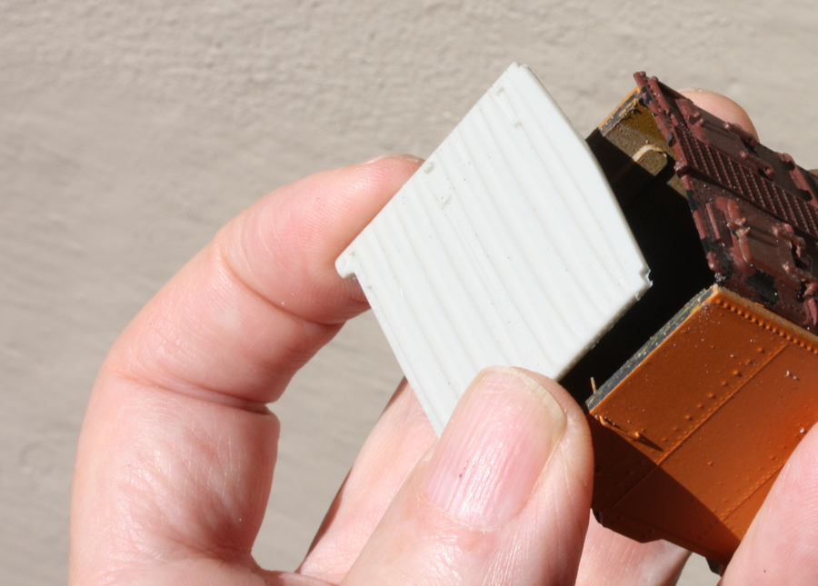
     The key point in this upgrade is the replacement car ends. My new ends are cast resin ones originally created for Westrail kits by Richard Hendrickson, and they are W-corner-post ends which are sized to fit the width of the Athearn reefer body. Because they do not have cast-on ladders, they also look better when fully detailed with free-standing ladders and other parts. Once the underside of the car roof is shaved off, the ends fit neatly in place. Here is a view of one of these resin ends.


These are just the right width to fit onto the Athearn car body, as you can see in this view (the roof has already been glued in place).


When I attach the end, a little putty may be needed along the top of the end to fit against the roof. But first all detail parts are added to the ends, then they are painted while still separate from the body—again, no masking!
    The detailing of these ends is straightforward, but it may be worth mentioning that the end ladders should match the rung spacing of the side ladders. The InterMountain refrigerator car ladders are very close (neither Red Caboose nor Tichy nor InterMountain box car ladders will work). I also used the placard boards and brake steps from the InterMountain 1937 AAR box car detail set (part 40700-59). Hand brake parts were specific to the particular class modeled. The second half of the 1000-car order for Class R-40-14 used Equipco brakes (first half Klasing); the second half of the 1000-car order for R-40-20 cars used Ajax brakes (first half Ureco).
     Here are an A and B end, with all details added and ready for airbrushing with boxcar red.


     Another point about the Athearn models, which many ignore but which is easily corrected, is the mirror image arrangement of brake gear. Athearn evidently misinterpreted the conventional mechanical drawing of the car underbody, drawn as though looking down through the underframe from above, as being a view from below the car. This puts the brake hardware on the wrong side of the longitudinal center line. At a minimum, it is easy to cut the Athearn parts away and simply glue them in their proper locations. Or better parts could be installed in their place. Adding brake rodding or piping would be an additional refinement. Here is one of my cars, as corrected (I used a styrene pad to support the cylinder). I simply rearranged the Athearn parts. Paint will be touched up.


     The paint and lettering schemes for these models have enough complications to justify description in a future post, and as part of that, I will attempt to address also the general topic of PFE paint schemes at particular eras. But readers should be aware that a much fuller presentation of these paint schemes is in the PFE book (Pacific Fruit Express, by Thompson, Church and Jones, 2nd edition, Signature Press, 2000).
Tony Thompson