Friday, March 10, 2023

Powering a few more switches

 It has been my philosophy from my earliest modeling days that any track switches that were hand-thrown on the prototype should be hand-thrown in my model trackage. This continues today. I have written a number of posts touching on this topic, including my recent one about adding more Bitter Creek throws on my layout (see it at: https://modelingthesp.blogspot.com/2023/01/installing-more-bitter-creek-turnout.html ).

But switches in difficult locations, either awkward to reach or merely distant from the aisle, present a problem with this philosophy. I do have a single switch at present that is powered, where industrial Track 7 diverges from the main line in my town of Ballard. (Background on Track 7 was described here: https://modelingthesp.blogspot.com/2019/03/putting-my-track-7-into-service.html ).

Awhile back, when I decided to power the switch that leads to Track 7, I realized I needed to surface-mount the switch machine, because there is staging track right under the switch. I used a relatively new product, an MP1 switch machine, as I described ( https://modelingthesp.blogspot.com/2019/02/powering-turnouts.html ) and have been quite happy with it. Here is a photo from the post just mentioned. A foreground tool house covers the machine when in use.

I have in addition two switches which are not only somewhat distant from the aisle, but also require reaching between buildings to operate manually. These are the leads to Jupiter Pump and Compressor, the track at left rear of the photo above, and just to its right (out of view in the photo above), the cannery track lead at Santa Rosalia. Here is a view of those two switches.

The switch at left, the Jupiter lead, is a Peco, while the one at right is a Walthers. The small section house at left is the same one as in the upper center of the photo at top. I have begun to carve two trenches for the operating rods. Also shown in this photo, a little left of the upper center, are the two MP1 switch machines that will be installed at the ends of the trenches. A structure will cover them when installed.

(In the photo above you can also see that I have not yet created any scenic treatment where the backdrop meets the layout surface. This is also planned as part of this project.)

Here is a perspective view of the area, somewhat like the view that a train crew would have, when needing to throw these switches. Obviously they have had to reach in between structures. This is what I want to eliminate.

To mechanically connect the switch machines with the track, I decided to encase the operating wire in brass tubing, so that the wire could be buried out of sight. That’s what the trenches are for in the photos above. For the tubing, I used K&S Precision Metals 3/32-inch brass tubing, their number 1144, and with it, some 0.045-inch steel wire. This wire is plenty stiff enough but slides freely in the tubing.

This wire-in-tube method is something I first used years ago, and it remains the operating system for the east-end switch at Ballard between the main track and the siding. The switch is located right behind the Wine Co-op building, thus difficult to see and all but impossible to reach to operate a ground throw. The photo below illustrates my solution: the red arrows show the turnout’s throw bar at top, and the Caboose Industries ground throw which operates it, at the bottom, via a wire in a tube below the ground surface.

I expect the same method will work fine for the new switch machine installation. As this project progresses, I will return to it in future posts.

Tony Thompson

Tuesday, March 7, 2023

A signal repeater for the layout

A couple of years ago, I posted a description of the yard entry signal that I installed on my layout, at the yard limit on my branch line as it approaches the yard at Shumala, California. It is a dwarf signal, and is aimed into a tunnel, where approaching locomotive crews can see it before exiting the tunnel, but of course this means that operators on the layout cannot possibly see the signal indication from the aisle. That post can be consulted at this link: https://modelingthesp.blogspot.com/2019/04/a-yard-entry-signal.html .

To repeat a view of that model signal, since it’s been a few years since I showed it, below is a view looking toward the yard, with the yard limit sign at right.


The way I decided that a signal indication could be conveyed to operators in the layout aisle is a repeater installation, which can show the color displayed (supposedly) by the dwarf signal. In this case, the indication would either be “stop,” red, or “proceed at reduced speed,” yellow.  

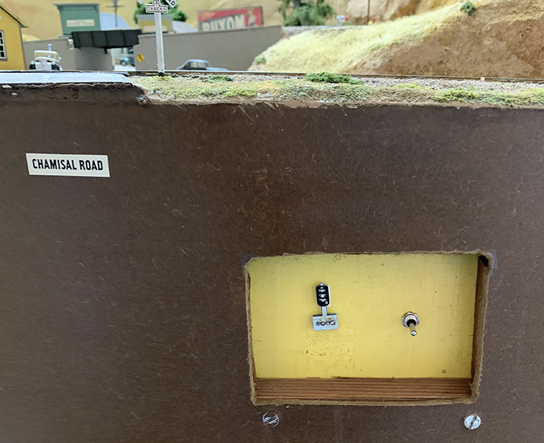
My first job for such an installation is to make a panel for the color lights, along with a switch for manual control of the signal indication. This should be recessed into the fascia so that a passer-by cannot bump the switch. I decided it should look like the nearby panel for layout power and throttles. That panel is shown below, with a yellow face for visibility.

I simply cut a rectangular hole in the existing fascia (well to the left in the view above), and added a yellow-painted piece of Masonite behind it, recessed with pieces of 1 x 2-inch lumber, as in the other panel.

At this point, the edges of the opening still need to be cleaned up, and the screw heads need to be painted to match the surrounding Masonite. 

What I wanted to install here is a “signal repeater” from Model Railroad Control Systems, in the form of their “simple low-cost signal,” the low-head “dwarf” style since that is what my layout model signal is (you can visit their site to see this item at: https://www.modelrailroadcontrolsystems.com/simple-signaling-and-accessories/ ). 

This repeater signal contains LED illumination. To power the LEDs, I provided 12 volts DC. The circuits for LEDs are not complicated; for those in need of a refresher or a first look, the Wikipedia article is a good resource: https://en.wikipedia.org/wiki/LED_circuit . 

In my case, though, my friend Seth Neumann (of Model Railroad Control Systems) installed the parts for me, with his expertise in both the circuits and the methodology of installation. When it was done, the panel looked like this (label not yet applied, edges of opening not cleaned up, and screw heads unpainted):

The toggle switch is center-off (double throw), so the repeater can be illuminated, either yellow or red, at the times desired by the yardmaster, or left un-illuminated. I made a label with black lettering on yellow, printed it on paper, cut it out and attached it with canopy glue.

Above is the final version, with the yellow LED lit. This panel will provide future yardmasters control over local freights arriving from the branch — provided I can train the local freight crews to watch for and obey the signal!

Tony Thompson

Saturday, March 4, 2023

Waybills, Part 106: briefing, Part 2

 In the previous post on this topic, I mentioned that Paul Weiss had inspired me to create a written version of the oral briefing I provide to visiting operators, before starting an operating session on my layout. The first part of the resulting write-up is here: https://modelingthesp.blogspot.com/2023/02/waybills-part-105-briefing-part-1.html . 

Having covered the basic waybill, and the Empty Car Bill, that are the primary documents that direct the movement of freight cars, I go on to some added features, all of which follow prototype practices.

First would usually be a waybill with a weight-agreement stamp and various handwritten notations on it, something that is quite common in prototype examples I have seen, and something I do with most of my model waybills. This is to convey that many waybills seen in a session are not pristine.

The most important document in this group is the perishable waybill. For many years, AAR recommended that perishable waybills be printed on pink stock. Southern Pacific was one of many railroads which did so (but it was not required, and a few roads did not bother). The majority of the form is the same as a regular freight waybill, except for notations about icing.

Note that this particular waybill has an “open” routing. This may well mean that the shipper feels it is likely that the load will be diverted to some other destination, evidently as soon as it reaches Ogden, as shown in routing. The “CPS” box (Carrier Protective Service) shows Section 2, which is normal bunker icing.

Next in my briefing would be a pair of tank car waybills. The waybill for the loaded car is a completely normal waybill, except the cargo is shown in gallons instead of pounds. But for empty tank cars that were privately owned (the vast majority of the national fleet), it was common for a regular freight waybill to be used for the return of the empty car to wherever its owner wanted it to go. This is an example.

Note that the “shipper” is just the local SP agent, not the original consignee. And note that the previous cargo (“L/C” means “last contained”) is also shown, a safety matter if the cargo was dangerous in any of several ways.

Next I would show a “switch” card, something I modified from a Union Pacific route card. (The original UP card is shown toward the bottom of this post: https://modelingthesp.blogspot.com/2016/07/route-cards-part-14-still-more-examples.html ). Here the intent is that the town’s agent is requesting the crew of the local freight to re-spot a car, usually because it was left off-spot by the previous crew. It is just inserted into the waybill sleeve for the car in question. Here it’s a Colorado & Southern gondola with a load of pipe.

Finally, I usually show a “memorandum waybill,” a temporary document that allows a car to start its journey to the consignee even though the regular waybill wasn’t filled out in time by the local agent for him to give the paperwork to the crew picking up the car. The actual waybill will be put into the mail, usually to the yard office at the junction where the car leaves the originating railroad, so the paper can accompany the car on its remaining journey, but sometimes to the agent at the car’s destination.

On the SP, this kind of waybill was called Form 704, as I described in some detail in a previous post (see it at: https://modelingthesp.blogspot.com/2021/09/waybills-part-91-model-form-704.html ). Here is an example, filled out by hand, which would be the usual usage.

This concludes what I normally present in an introductory waybill briefing before starting an operating session. Occasionally other forms do show up in the briefing, if needed, but this is the basic set of documents that operators will encounter and need to understand.

Tony Thompson

Wednesday, March 1, 2023

Modeling SP passenger cars, Part 12

 In previous posts in this series, I have addressed a wide variety of Southern Pacific passenger cars, many of them head-end cars. (Previous posts are easily found by using “modeling SP passenger” as the search term in the search box at right.) Although some SP passenger cars may appear generic, in fact the great majority had individual characteristics, especially the Harriman-era heavyweight head-end cars. 

In the present post, however, I want to turn to streamlined sleeping cars. This is a kind of follow-on to the extended description I published about heavyweight sleeping cars, in an article for Model Railroad Hobbyist (see a description at: https://modelingthesp.blogspot.com/2023/01/my-new-column-in-model-railroad-hobbyist.html ). That article focused on conversions of Rivarossi (or AHM) Pullman cars to floor plans other than the original 12-1 (12 sections, 1 drawing room).

The corresponding Rivarossi streamlined sleeping car represents one of the 10-6 floor plans (10 roomette-6 double bedrooms) for these cars. But there were a number of other floor plans widely used. As with other passenger car topics, one needs to learn what preferences and practices were followed by the railroad that is chosen for modeling. We SP fans have a great source: Volume 2 on sleeping cars, from the five-volume series of books entitled Southern Pacific Passenger Cars and published by the SP Historical & Technical Society.

Two distinctive cars used by SP for years on the all-Pullman overnight Lark train were the 13 DB (13 double bedrooms) and 4-4-2 ( 4 double bedrooms, 4 compartments, 2 drawing rooms). Both have distinctive window patterns and are readily recognized, thus desirable for modeling. For example, below is a photo (Lawson K. Hill, San Francisco, 1953) of SP 9106, a 4-4-2. 

This is the bedroom side of the car, and the distinctive pairs of small upper windows, one pair for each compartment, are evident. The two drawing rooms are the pairs of windows between the compartments, and the other windows are the double bedrooms. Note also the location of the remains of the original full skirts, below the compartments.

The 13 DB car has pairs of large windows on the bedroom side, and somewhat evenly spaced ones on the aisle side. But the aisle side also had some remnant skirting, as is shown below, in a photo at San Francisco circa 1955 (Don Munger collection). This photo and the one above, both showing cars in Lark service, are from the SPH&TS Volume 2 on sleeping cars.

To model the floor-plan cars just shown requires purchasing brass cars, or starting with some other car body and replacing the sides. Replacement could be done by scratchbuilding styrene car sides (actually not terribly difficult, since the car sides were entirely smooth). But an even simpler solution exists: brass replacement car sides.

Starting in 1978, Dennis C. Henry has operated a company called Brass Car Sides (you can visit their website for considerable information at: http://brasscarsides.com/ ). The coverage is most extensive for Great Northern, Northern Pacific and Milwaukee Road, but reasonably standard Pullman cars for many other railroads are available too. These are intended to be attached to some kind of core body.

As you see below, I purchased sides for the 13 DB (upper pair) and 4-4-2 cars (lower pair). The aisle side of the 13 DB car is the lower side of the pair, while for the 4-4-2 it is the upper side. You can observe that the remnant skirting on the brass sides matches what is shown above for the prototype 1950s Lark cars.

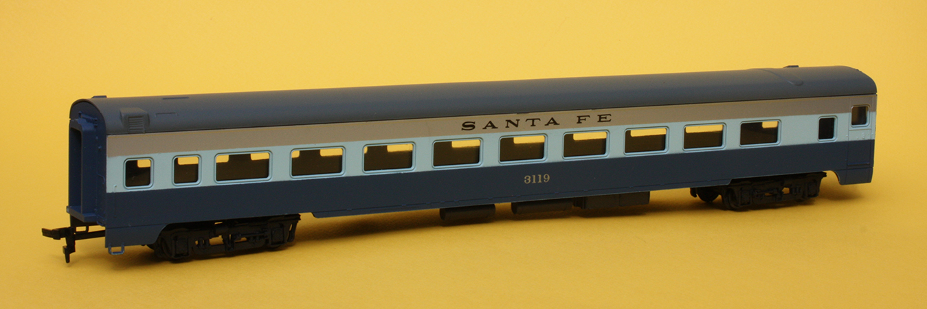
These particular sides are intended to be used with an Eastern Car Works “core body” kit, and are slightly too short for a Rivarossi body. However, there are easy solutions to this, which I will pursue since I have a stash of the Rivarossi streamlined cars. For example, here is the Rivarossi streamlined coach. This is one of the car bodies I will transform. Window arrangements here don’t matter — they will all be replaced!

For a good illustration of using these car sides to apply to a Rivarossi core body, I recommend the article by Willard Harvey (Mainline Modeler, Volume 11, October 1990, pages 68–73). He did what I will do: simply remove any area of the window band that conflicts with the new sides. Remaining parts of the side provide a foundation  to support the new sides. And one nice feature: since the new sides are thin, the window glazing can lie almost flush with the car side, as it should.

For more recent (and probably more accessible) articles, see the Brass Car Sides site. Among the write-ups there is this one, which I found interesting and informative: http://brasscarsides.com/photos/Jim%20Schwinkendorf/BCS%20Grove%20Car%207-4-20.pdf . Another quite informative article by Jeff Hanson is worth reading (see: http://brasscarsides.com/Construction%20methods%20for%20brass%20car.pdf ), but uses a Walthers car body to make a Budd car, so somewhat less relevant to my two projects.

I will continue with the model work in a future post.

Tony Thompson

Monday, February 27, 2023

Home Shop forms

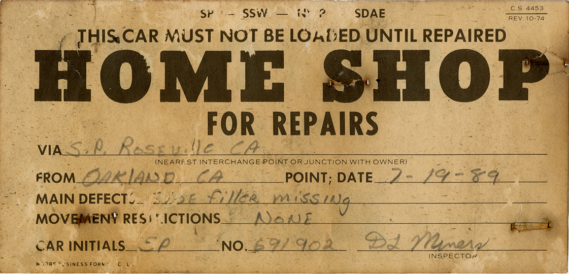
For decades, prototype railroads have used a paper form intended to route a damaged car to its home shop for repairs. Usually of a size to be stapled to a route card board, they were usually light card stock. I thought this might be a good form to introduce on my layout. 

(For background on route card boards, you might wish to look at this post: https://modelingthesp.blogspot.com/2011/11/chalk-marks-and-route-cards.html , with more information on the actual AAR standards for such boards described at this link: https://modelingthesp.blogspot.com/2011/12/route-cards-6.html .)

Here’s a Southern Pacific example of such a Home Shop form, well darkened by being out in the sun and weather until I rescued it from a car body with no trucks (thus probably no longer headed somewhere). The original is 3.25 x 7 inches in size.

The back of this card is interesting: it can serve to direct a car’s location in a train, for example a very light car might well be handled preferentially at the rear of the train. I will have to give some thought to whether I can use this in model form.

The card is a little damaged and quite dark in color. But of course in Photoshop all that is fixable. I lightened the background, removed the pencil writing, and repaired a few damaged areas. This gave me a starting point I could use.

Next I removed the part of the image that wouldn’t fit with my era, namely the four railroads listed at the top of the form (SP, SSW, NWP, SDAE). I then sized the image so it would fit into my waybill sleeves, which are baseball-card-collector sleeves, with a long dimension of 3.5 inches. This could now be printed out for use in an operating session.

To illustrate, here’s a yellow Empty Car Bill, overlaid with a filled-out Home Shop card. This doesn’t change how the car will be handled in my operating session, but it makes a different direction being given to the crew. The variety seems like a good feature. On some layouts, with foreign-road interchanges, or with main yards that direct empties for loading, this could change car handling. 

I filled this out in ink for visibility, but most prototype examples I have seen were filled out in pencil. I will experiment with a soft pencil to see if that can be more visible. The prototype form is over twice as big and so writing is easier to read on it.

I should mention here that I do have a prototype SP bad-order card in use on the layout, as I have described previously (you can see my post about it at: https://modelingthesp.blogspot.com/2018/04/a-new-bad-order-card.html ). But because it is “nice looking,” as one person put it, visiting operators don’t like to use it to designate cars that need work. I like the “Home Shop” card because it can be used to move cars or to indicate bad orders.

I should also show an example of a Home Shop card from another railroad, in this case Santa Fe. I found this on a car not at Stockton, as the card mentions, so either the car was continuing to be moved, or had been repaired and the card not removed. This card is 8.75 x 3.75 inches in size.

The back is quite interesting; it is a Bad Order card, so obviously a carman could use whichever side suited his needs. It calls for quite a few specific indications of why the car is bad-ordered, and is of course a rather eye-catching color (the original is more of a fluorescent orange).

I will return to the topic of ways such cards could be used in model layout operation, along with results of my own experiments, in a future post.

Tony Thompson

Friday, February 24, 2023

Modeling in O scale, Part 2

Though a confirmed HO scale modeler from the very beginning of my model-building career, I do have a soft spot for O scale models, especially freight cars. As I mentioned in the previous post in this series, they do make me “itch” as a modeler who likes freight car details (you can see that post at: https://modelingthesp.blogspot.com/2023/02/modeling-in-o-scale.html ).

In the previous post, I showed two of my O scale models, an Athearn metal box car (originally owned by Paul Shimada) and a styrene PFE steel reefer from InterMountain. Another Athearn metal model that I especially like (as a confirmed Southern Pacific modeler) is a 40-foot car decorated for SP’s “Overnight” service, the famous black box car scheme.


 One of the really nice things about this Athearn metal car (and also for the HO scale version done by Athearn in a metal kit) is that the trouble was taken to make new pressed ends, with the post-war “Improved Dreadnaught” contour, not true of other Athearn metal box cars. And not only that, but new sides were made too, to correctly show the ACR (Alternate Center Rivet) pattern of the side sheets — also done for the HO scale version in metal. Here’s a photo:

Another model I really enjoy owning is another Athearn metal car. It represents one of the two PFE rebuilt cars in Class R-40-14, but with nearly all aluminum bodies. And as one can readily prove with a magnet, the model’s sides are actually aluminum. Now PFE only had two of these cars, in a fleet of nearly 40,000 cars, but it will certainly grace my display case. It is modeled with its original 1946 paint scheme.

The underframe and all safety appliances, such as ladders and grab irons, were steel and painted black, as were door hinges and latch bar. It’s a lovely model of a distinctive PFE car.

Last, I want to show a little about an SP tank car model from Pecos River Brass. I wanted to letter it correctly, and as it happens, back when I made the artwork for SP tank car decals in HO scale (first sold by Jerry Glow and now by Tichy), I also made one set that was in O scale. Here is a link to the first post about the decals: https://modelingthesp.blogspot.com/2011/05/sp-tank-car-decals.html .

Shown below is the model, with decals freshly applied and a coat of flat finish sprayed on. Couplers are removed for the weathering step, which is next. As you can see, it has an operating manway cover on the dome.

Next came weathering. I followed my usual method using washes, with pigment from acrylic tube paint, but realized one more time how very large O scale cars really are, for someone accustomed to the size of HO scale cars. If you’re interested, background and illustration of my weathering process can be found in the “Reference pages,” linked at the upper right corner of the present post. This view of the right side of the car reminds that this side of SP tank cars had neither dome walk nor ladder.

By contrast, the other side does have the single ladder and dome walk, and in this case I’ve applied an “empty” placard as well.

All three of these O-scale models represent prototypes that are very familiar to me, as an SP and PFE modeler and historical researcher and writer. All are a pleasure to own, and also will soon be displayed in a wall display case. That will be nice!

Tony Thompson

Wednesday, February 22, 2023

Operating sessions no. 80 and 81

 This past weekend I hosted a pair of operating sessions on my layout, and these were sessions no. 80 and 81 on the layout in its present form. That’s not a fact of any importance, just a passing mention. The reason for the session was as a tune-up for the forthcoming BayRails event for out-of-town operators in March. 

(For those interested, I have written about BayRails previously. This event is held in March of odd-numbered years, and the 2023 edition will be the ninth in the series. The post about the eighth event in 2019 [we skipped 2021 for obvious reasons] is here: https://modelingthesp.blogspot.com/2019/03/my-sessions-at-bayrails-this-year.html .

My layout was also involved during an earlier BayRails, the seventh event in 2017, and there’s a write-up for that, too, which can be found at this link: https://modelingthesp.blogspot.com/2017/03/bayrails-2017.html . But the point of the present post is to describe my tune-up for the 2023 event.)

The first day, my crew comprised Pat LaTorres, Dave Stanley, Jeff Aley, and John Sutkus. As crews nearly always do, they paired off and each pair started on one side of the layout, moving to the other side when the second branchline train ran. Here are Dave (at left) and Pat, getting close to finished with their switching at Shumala.

Meanwhile, on the opposite side of the layout, switching Ballard, was the other pair of operators, Jeff Aley (left) and John Sutkus. As I recall, Jeff was the engineer for this part of their work, and John was conductor.

I must admit we found a few problems, including a loose point rail in a switch and another point rail that had become slightly bent and no longer touched the stock rail when the switch was thrown. These were addressed in the evening after the session. These are trackwork elements that have been in satisfactory use for a considerable time, but as the Providenza maxim reminds me, “Trust nothing.”

On the following day, the crew comprised Mark Schutzer, Ed Slintak, Seth Neumann and Richard Brennan. They of course benefited by the flaws found and the problems corrected from the previous day, and happily, new ones were not found. Shown below are Seth (at right, checking on a point of information). He was the conductor at this time — note the clipboard with switch list. Richard Brennan, at left, was the engineer here.

Meanwhile, Mark and Ed were hard at work on the other side of the layout. Below you see them sorting out a long string of cars at Shumala. That’s one of Mark’s very nice SP 0-6-0 switchers, working at Shumala today, by Ed’s left hand.

One of the interesting parts of every session is the return of the first branch train to Shumala. Its power has to be exchanged onto the next train outbound to the branch, and the caboose likewise has to be transferred to the new train. This can be done in quite a few ways, some much simpler than others. Below you see Richard and Mark figuring this out. The long string of cars with the caboose is the arriving train, and on the track to the right of it is what will be the outbound train. The arriving road power has just been cut off and is moving out of the way so the Shumala switcher can exchange the two consists.

Two good sessions, a number of flaws found and (I believe) fixed, in advance of BayRails next month. But I’ll continue to exercise the trackwork in the meantime, reminding myself as I do so, to “Trust nothing.”

Tony Thompson