Thursday, November 29, 2018

Small project: installing an etched-metal running board

I have been gradually working through my several Southern Pacific box cars of pre-war built dates, and replacing their original Red Caboose or InterMountain wood running boards with etched metal “steel” running boards. The first box cars that SP purchased, according to the 1937 AAR standard box car design, were from classes B-50-18 and -19, and these were delivered with wood running boards.
     But by the beginning of World War II, three more classes of box cars had been delivered, totalling more than 5200 cars, and all had steel running boards, as well as W-corner-post ends. Bodies with these ends have been offered by Red Caboose and InterMountain, but the steel running boards have been ignored, and all these car classes have been produced with wood running boards.
     As my layout centers on SP, I wanted to correct these models. I will just show a single example of how I do this. I have several sources of etched-metal running boards, including some nice ones offered by Overland Models years ago, but the versatility and general excellence of the Plano Model Products boards is very convenient. Shown below is the kind of kit you get, with the longitudinal running board, and both lateral boards in a single fret, and a frame for the laterals (below the laterals’ fret in the photo below), This is a kit for an Apex running board.


You can see all these parts here, though the full length of the longitudinal board extends under the label at the top.
     My first step after removing the old, incorrect wood running board, is to attach the longitudinal board with canopy cement. This is the right cement for this job, because it remains flexible and will not break when temperature changes expand or contract the metal running board; the contrary is true of CA or other brittle adhesives. (For some further details about canopy glue, you might wish to read my blog post on the topic, which can be found at: https://modelingthesp.blogspot.com/2013/05/a-few-words-in-praise-of-canopy-glue.html .)


I have represented a little paint failure on this roof, using a light gray paint at sharp edges of the roof panels, which is where paint over a galvanized surface often fails.
     Note that this running board on the model is a U.S. Gypsum board, also from a Plano kit. The car models SP 82940, Class B-50-21, and out of 2000 total cars, the 500 cars of this class built by Bethlehem (SP 82490–82949) all had Gypsum running boards. (This information is from my Volume 4 on box cars, in the series Southern Pacific Freight Cars, revised edition, Signature Press, 2014.)
     Next I attach the frames for the laterals to the back of the lateral boards, using CA. Shown below are the undersides of the laterals with frames attached. All application of CA is on the underside only.


     The next step is to attach the corner grab irons to the laterals. I used Tichy corner grabs for this, and added eyebolts from my parts box. The way I arrange a constant height of the grab iron above the lateral is to clamp a piece of styrene between the grab and the lateral (using a normally-closed tweezer), then apply CA underneath to hold the wire ends of the grab and eyebolt. The clamped arrangement is shown below. In the photo below, I  moved the tweezer slightly so you can see the grab iron.


     With this completed, I cut off the excess length of the grab iron on the underside of the lateral, then bent the frame tabs to accommodate the shape of my model box car roof. I attached both laterals with CA. This completes the modeling work for this job.


     The rest is finishing: painting the running board with boxcar red, then weathering lightly to match the roof. But that is straightforward and not an essential part of this small project. I have more of these Red Caboose box cars to “correct” by replacing their wood running boards, so this is kind of a pilot project for additional work.
Tony Thompson

Monday, November 26, 2018

Tie piles and rail racks

Every railroad, large or small, maintains roadbed, and it is a never-ending job. Sub-roadbed may sink, drainage channels may fill with debris or collapse, mud may intrude into ballast, and rail alignment may degrade. Wood ties slowly deteriorate, rail gets worn, even concrete ties have a finite lifetime. One sign of this ongoing challenge for track forces is the storage of new ties and rail alongside the track. Ties may often be seen stored at trackside, since ties deteriorate at varying rates. Rail may be stored in areas requiring relatively frequent replacement, such as sharp curvature areas, but it may also be stored at section houses and other prescribed locations.
     Railroads typically have a standard way of storing rail and ties, though of course the “standard tie pile” or rail rack may not always be observed. Railroads with extensive standards of all kinds, such as Southern Pacific with its very many Common Standard (CS) drawings, would be expected to have standard tie piles and rail racks, and in fact they did. You can find the drawings in Bruce Petty’s excellent five-volume series, Southern Pacific Lines Common Standard Plans (Steam Age Equipment Company, Dunsmuir), containing many maintenance of way drawings. specifically in Volume II, page 67. A scan can’t do justice to the original, but here is a copy of CS 1901, last revised in 1930. (You can click on the image to enlarge it, if you wish.)


It may be of interest that new ties are stacked differently whether creosoted or untreated. Note at lower right that “fuel ties” are included. These were old, replaced ties suitable only for fuel use, not to be re-used in track. Note also that the number of ties per pile is “variable.” Finally, the piling of new, untreated ties is interesting, because at each pile layer edge, a tie on edge instead of flat helps make air space in the pile.
     There was also a standard rack, and rack location, for stored rail, as seen below in a copy of drawing CS 553, a 1950 standard (on page 73 of Volume II). The rail supports are four-foot lengths of second-hand trestle stringers, 8 x 17-inch timbers, but note that they are set on edge, and half-buried. Thus the exposed height of this timber is only 7 inches (see transverse section A-A), so that its surface appearance is essentially a 7 x 8-inch timber.


The Notes to this drawing specify that racks are to be located at ends of sidings, but not closer than eight miles apart on main lines. Rail may also be stored at section houses, probably in the same manner.
     Both of these standard arrangements are very easy to model, and will make an appropriate addition to scenery in suitable places on my layout. I will show my modeling approach, and layout locations, in a future post.
Tony Thompson


Saturday, November 24, 2018

Thoughts on visiting layouts

This past year, I have attended several layout operating weekends. Of course, I go mainly for the experience of operating on a range of quite diverse layouts. But part of the experience is also the simple pleasure of viewing impressive layouts up close and in detail. I always enjoy these events, and typically have several really good operating sessions, but the diversity of the layouts always leads me to mull over what layouts can show you, as well as the ways you can learn from them.
     Some readers will notice that I characterized the layouts visited as “impressive.” Are they all of the quality that has been in (or should be in) publications such as Great Model Railroads, the Kalmbach annual magazine? No, a fair fraction of them aren’t that kind of layouts. So why did I call them “impressive?” The simple reason is that there is so much to see in even a modest layout, so much that the builder has done, so many problems solved in invariably interesting ways, that I always find it a rich experience.
     I once remarked to someone, that a layout is such a personal expression, so revealing of its builder, that one might feel surprise that owners even let us see them. Of course the personal part is neither embarrassing nor really private, but it certainly is individual. This extends to so many parts of the layout: its design, its quality of trackwork, its scenery and structures, the rolling stock, and even to the choices of operating procedure and car movement system. All these features are best appreciated during operation, when the layout “comes to life” as (presumably) the builder intended, but even a brief visit can yield considerable insight.
     To choose just one example on the operating side, which happens to be one of the finest layouts in the country, I always enjoy an invitation to operate on Bill Darnaby’s Maumee Route in the Chicago area. So much of the layout reveals careful thought and planning, and so many details jump out at you, that it is almost hard to appreciate it all, and I would say multiple visits are needed to really grasp what is there. Just as a single illustration, shown below is Phil Monat, who was yardmaster at the Maumee’s East Yard (at lower left), during a session last October.


Phil looks cheerful, though I know he was kept quite busy running this active yard!
     But a layout need not have the extensive completeness of the Maumee to be both interesting to operate, and interesting to understand, as a layout design. I mentioned Rick Watson’s excellent Southern Pacific Exeter Branch layout in my post about Desert Ops 2018 (you can see that post at this link: https://modelingthesp.blogspot.com/2018/11/desert-ops-2018.html ), and here is another view of it, showing part of the yard in Exeter.


This is not detailed or scenicked, and the industries are minimally represented; but note on the wall, there are detailed and specific maps to guide switching moves. There is in fact much to learn here, even if it is not the “conventional” beautiful layout.
     I have often mentioned to people, that I can’t remember ever visiting a layout, even the ones at the stage of plywood and track only, without learning something, or seeing something interesting, or getting an idea that I can use. That is just another product of how much of a layout owner is poured into the layout, even in its early stages.
     To choose just one instance of what I’m talking about, I visited Paul Chandler’s outstanding SP layout in Tucson as part of the Desert Ops visit last month. He has modeled something I need to include on my layout: pullouts for motor cars or hand cars. The photo below shows an example from his layout. This is simple, familiar from the prototype, yet not often modeled. I will definitely do a few of these for my layout!


     The message here? Layout visits are always worthwhile, even early in a layout’s life. And when you walk into a layout room and see minimal scenery, don’t stop looking. There is a lot to see and learn, at every stage of layout development. You will get ideas, usually multiple ideas, from every layout you visit, even if you don’t get a chance to operate. So do visit layouts when you get the chance, and make the effort to see what is distinctive and original about every one. You may be surprised how much you learn!
Tony Thompson

Wednesday, November 21, 2018

Route cards, Part 17

Awhile back, I presented four posts with examples of prototype route cards sent to me by Ralph Heiss. Last spring, I met Ralph at an operating session in New Jersey, and he handed me still more examples of these interesting prototype documents. This post presents them. To see the fourth post in that previous series, use this link: http://modelingthesp.blogspot.com/2016/07/route-cards-part-14-still-more-examples.html .
     I begin with a few Southern Pacific cards.The card numbered 48 is for SP 49559, a 52-foot flat car with straight side sills, Class F-50-14, delivering a carload of lumber to a lumber yard in Downey, California. Like all the SP cards in this group, it is 3 x 4 inches in size.


     Next is card 51, for SP 83022. It is only identified asd a “load” without other information. Even the dat is only shown as the day of the month (16). The year, as with all these cards, is 1956. The car is a 40-foot box car of standard 1937 AAR design, SP Class B-50-21. The tears in the card when it was removed from the car suggest that it was tacked, not stapled. Both methods were in widespread use in the 1950s.


     Another example is card 76. It is for empty PFE 40198, a steel reefer of Class R-40-10. It is evidently a transfer car, as its destination is the Pacific Electric’s Butte Street yard. On this card, the date is stamped as March 9, 1956. Note, as with all these SP cards, that the Common Standard document number at upper right is 79xx, where xx is the large number on the card.


     Next I show card 95, which is for another PFE steel reefer, PFE 6027, a member of Class R-40-23. The card is dated February 25, the car is loaded with perishables, and is destined to Chula Vista, California, which is on the Santa Fe, south of San Diego.


Interestingly, the corresponding Santa Fe card was also retrieved by Ralph Heiss, likely with both of these cards attached on top of one another. This one was the later of the two, as it is dated February 27. Like many Santa Fe route cards, it is 3 inches square, and is a San Diego card. That likely means that the SP interchanged the car to the Santa Fe in Los Angeles, Santa Fe delivered it in a through freight to San Diego, and now a local freight will move it from San Diego to Chula Vista.


     As always, I find these cards fascinating, and thanks again to Ralph for providing them. They are only little pieces of the process of moving freight cars to destinations, but reveal how the process worked. In model form, we try to represent these ubiquitous cards on the route card boards of our freight cars. The ones shown in the present post all have pretty big numerals, and I am experimenting with getting numbers like these onto HO-scale pieces of paper. Not sure it is going to work — but I will report on the effort in a future post.
Tony Thompson

Sunday, November 18, 2018

Hendrickson auto car, Part 6

My previous post about my progress in completing this project of Richard Hendrickson’s, a Santa Fe rebuilt automobile car of Class FE-25,  can be found at: https://modelingthesp.blogspot.com/2018/06/hendrickson-auto-car-part-5.html . With the car body completed (as shown in that previous post), I was able to move on to painting the car. As I commented in Part 3 of this series, a complication in such car painting is that Santa Fe added black non-skid coating to roofs at the time of this rebuilt, though wood running boards were body color. (You can see Part 3 at this link: https://modelingthesp.blogspot.com/2018/03/hendrickson-auto-car-part-3.html .)
     When it comes to paint for Santa Fe freight cars, the careful modeler wants to approximate the prototype color. My late friend, Richard Hendrickson, as dedicated and serious a Santa Fe freight car modeler as you could find, always used Floquil “ATSF Mineral Brown” paint for his Santa Fe models, and I happen to have inherited a couple of his bottles of that paint. I proceeded to airbrush the entire carbody that color, and also to paint the Proto2000 running board at the same time.
     [For anyone who does not know, or has forgotten, who Richard Hendrickson was, it might be of interest to read the memorial essay of tribute I wrote after he passed away in June 2014. That essay can be found here: http://modelingthesp.blogspot.com/2014/07/in-memoriam-richard-hendrickson.html .]
     With that done, I brush painted the roof with a dark gray color I like, Tamiya XF-63, “German Grey.” The original Santa Fe’s car cement was black, but with age and weathering, I thought the dark gray would be a better starting point. Once that was dry, I attached the running board with canopy glue.


The model here is still on temporary “truck support blocks,” which are an effective way to handle and paint a model without trucks (see a description at: https://modelingthesp.blogspot.com/2014/11/interim-truck-support-blocks.html  ).
     Because the car could represent a seriously weathered car in service with an original 1942 paint scheme from the rebuilding, I thought about the opportunity to “pre-weather” it before adding decals, so that the white lettering would stand out against the dirty body paint. This is commonly observed on prototype freight cars in the transition era, usually attributed to the white paint “chalking” and sloughing off some of the dirt. To do that, my next step would be a coat of flat, for my water-based acrylic-wash method of weathering (see the Reference Pages, listed at the top right of this blog post page, for more on the method), followed by a gloss coat and decals.
     But since Santa Fe kept these cars in automobile service, either with racks for assembled autos or with auto parts racks, and did renumber them to suit each service, I decided I should choose instead a post-1947 paint scheme, with the “Ship and Travel” legend replacing the system map on the right sides of cars. All pictures I have seen of the FE-25 cars show one of the two “El Capitan” slogans, so that was chosen for the left side. With a coat of gloss on sides and ends, I was ready to apply decals.
     The other omission that might be evident in the photo above is that I had not added the placard boards and route card boards on the car doors. I wanted to get a good, uniform coat of paint under those boards, so I had planned to add them after base painting. I had a couple of extra placard boards from other projects, and simply made route card boards from lengths of scale 1 x 6-inch styrene. As I noted in a previous post, the rules on these boards specified a minimum size of 5.5 x 9 inches (you can read that post at: https://modelingthesp.blogspot.com/2011/12/route-cards-6.html ).
     Lastly, the photo above shows the car without trucks or couplers. These cars kept their Andrews trucks when rebuilt, and many continued to ride on those same trucks into the 1950s, so I chose that truck type for this model. I also added my current standard coupler, Kadee No. 58.
     Once decals had been applied and protected with a coat of flat finish, I proceeded to use my usual methods of acrylic washes, mentioned above, to make the car moderately dirty. It’s a post-1947 paint scheme, so need not be terribly dirty in my modeling year of 1953. Here is the left side of the completed car, ATSF 9302, a car renumbered for cars in service with Evans auto loaders.


The right side (below) has of course the other slogan, as well as the transverse-mounted brake reservoir, visible just to the left of the right-hand truck, with its servicing stencil. (You can click to enlarge.)


     Lastly, I wanted to indicate what was happening to this group of cars in the early 1950s. Some of the cars began to have loaders removed, and when that was done, the white stripe on the right-hand door of loader-equipped cars was simply painted out. I used a brighter shade of boxcar red to paint this by hand with a small brush.


     This completes work on this project that Richard Hendrickson started. I enjoyed figuring out where he was headed, and I hope he would have been pleased with how I have managed to finish the model. The car is already part of my auto parts train for the next operating session.
Tony Thompson

Thursday, November 15, 2018

Trackwork wars, Part 3

An important part of maintaining a layout over the long term is, kind of surprisingly, trackwork. That’s surprising because, yes, you built it carefully and it has operated well for years. And then something — ah, if only one knew what that something was — goes wrong. I have alluded to this point in several previous posts; the most recent in my “wars” series was last July (the post is available at this link: http://modelingthesp.blogspot.com/2018/07/trackwwork-wars-part-2.html ). And as it happens, that previous post was about track gauge in a Peco turnout.
     Most recently, in my last operating session a month or so ago, I had a different Peco turnout go bad, largely from the gauge getting tight. This was a surprise, as the turnout was installed in early 2015 and has performed flawlessly ever since. But in operating a locomotive and cars in all areas that have ever given any problems, I started getting derailments on this turnout. I usually do this testing before an operating session, but in this area, in the town of Santa Rosalia on my layout, I was doing it the day before the session, since I had not anticipated a problem.
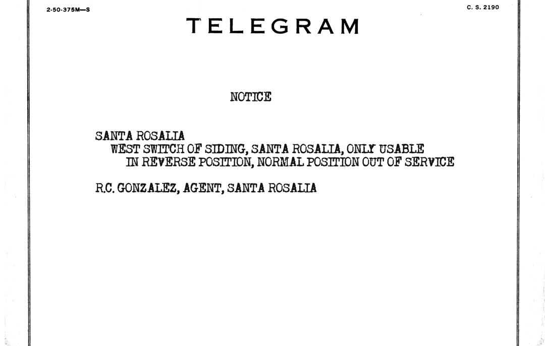
     I tried to file the rail within the turnout, to widen the gauge that had narrowed. But I quickly discovered that the gauge had only narrowed in one part of the turnout and was, if anything, wide in the remainder of the frog area. I attempted to nudge the offending rail into position and add more spikes to hold it, but this was not working very well, With the operating session imminent, I had only one choice, and that was to make one side of the turnout “out of service.” I did so with the notice below.


This is my usual form of my messages from a station agent to the operating crew, using the SP company telegram blank (since agent’s desks in the 1950s had heaps of pads of these telegram blanks, and agents often used them for notes).
     As I reported for that particular operating session, everything planned worked out all right (my post describing that op session can be found at: http://modelingthesp.blogspot.com/2018/09/operating-with-more-features.html ), and crews switching at Santa Rosalia simply had to plan ahead to position cars in the train they took there from Ballard, as the switch being out of service in the normal position meant that there was no longer a run-around available at Santa Rosalia.
     But of course this was only a temporary solution. The switch had to be replaced. I did communicate with the Technical Advice people at Peco, who are always responsive, as to whether I might have done something wrong in installation, to cause the track gauge to change. They replied that they did not think so, and asked me to return the offending turnout to them for examination. I went ahead and mailed it to them. Meanwhile, I pulled out the turnout, as you see below. Luckily, only part of it was ballasted, making removal fairly easy.


     The next step was to purchase a new switch. Although Peco might have replaced the switch, I decided not to wait for the outcome at Peco, and bought a new one. (Ultimately Peco did not offer to replace the switch.) There is inevitably a bit of jockeying to fit a new switch into existing trackwork, to make sure all the abutting tracks line up smoothly, and this took some time. But I finally got it into place.


This photo show the switch in place, though rail joiners are not yet soldered, nor is the feeder (blue wire, near right center of photo) attached yet. Obviously the rail will need to be painted also.
     Once the turnout was in place, the rest of the installation was completed easily. All rail joiners that previously had been soldered were re-soldered, and the feeder was re-installed. Then I used Tamiya “Red Brown” (No. XF-64) to paint the rail sides. Here you see me in the process of painting.


The building at right is Pismo Marine Service, a ship chandler in my town of Santa Rosalia. It was described as part of another post about use of KingMill photographic flats (that post is at: https://modelingthesp.blogspot.com/2015/09/jupiter-pump-and-compressor.html ). 
     This problem has been solved, though it was more trouble to do than I expected. I have no idea what was the cause of this defect, but the important point is to fix it, not to diagnose it. I just hope it won’t recur. I really don’t like having to fix track that gave every indication for several years that it had been installed well in the first place!
Tony Thompson


Monday, November 12, 2018

The newest Tony Koester book

As many have no doubt noticed, new Kalmbach books from author Tony Koester come along pretty regularly. This is not an accident, as Tony is under contract to produce these books at an agreed-upon interval. But with his authorial skills and generally outstanding photo selection, they tend to be excellent books, regardless of the subject of any individual one.
     The newest is about engine terminals. and it is indeed as good as we would expect. I show the cover below, identified as part of the series, “Layout Design and Planning,” and indeed, the book is packed with ideas for how to arrange the necessary facilities for model engine terminals.


     A modeler may think, “I already know what engine terminal(s) I need,” and probably he or she already has a good idea of what should be included. But there are a great many details in this subject, and a book like this can help ensure that nothing essential is omitted. And of course you may get ideas for how to model particular details.
     The book covers its subjects in nine chapters. from initial chapters about fuels and roundhouses, to chapters about mainline servicing, diesel houses and car barns, and what’s called “the short, the narrow and the regional,” referring of course to the facilities  of smaller and financially strapped railroads. Concluding chapters describe how power was fitted to assignments, how engine servicing gives rise to model layout jobs, and finally a nice pair of examples in which prototype facilities are adopted to model use. A concluding photo gallery adds still more information.
     In most books, I find at least one photo that really jumps out at me (not always for the reason intended by the author). Sometimes it’s just an image I like. But when these favorite images suggest something I can benefit by doing, or change something I already do, they are doubly valuable, In this book, one of the prototype engine terminal shots caught my eye, not for its intended meaning, but for something included in the photo (photo by Chris Guss). It’s the Lake State Railway in Saginaw, Michigan.


The reason I like this? Note the weeds growing around the edge of the turntable pit, and the scattered grass or weeds growing around the garden tracks. (You can click on the photo to enlarge it if you wish.) This looks so good, that it cries out to be modeled, and any modeler would envy the look, yet it would be very easy to do. You just have to notice this detail in the photo, and realize you could do it too. When a book gives you, not just one, but several such inspiring images, it is worth far more than its mere purchase price.
     As you can tell, I have enjoyed reading, and even more being inspired by, this book. Like practically all of Tony K’s books, it’s excellent value, and I recommend it highly.
Tony Thompson