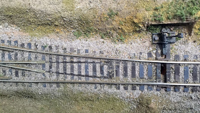
That preceding post showed the removal of the point-rail assembly and cutting off of the closure rails, along with cleaning up the tie strip. The next steps were to install the new parts to replace the old, removed parts. The method described, I should explain, is suitable for turnouts already in place on a layout. Some of the required work is more easily done on the workbench, but usually one’s really old Shinohara turnouts are already installed in the layout. Work illustrated in the preceding post showed practicing on a turnout not installed, but the goal was to fix an installed turnout.
As I showed in Part 11, all point rails were removed back to the area of the frog. The first step in applying new parts is to clean up the cut rail ends with a file, and install rail joiners that fit the rail size. This turnout in the SP main line on my layout is code 100, so that is the joiner size (you can click to enlarge).
This is a right-hand turnout, whereas some of the prior photos were for a left-hand turnout; but of course all the procedures are the same.
Two pieces of rail, the code 100 size of the turnout, are now cut (overlength). One side is filed flat and the head of the other side also filed flat, to serve as points. Of course remember there is a “left-hand” and “right-hand” point, so don’t make the common error of making two alike (you can guess how I know). Then the stubs salvaged from the old point rails, as shown in Part 11, are soldered to the inside base of the point rail. Next a clearance hole is drilled in the stub to accept small assembly screws, such as 0-80, 00-90, or 1.2 mm (I used the latter). I will say more about assembly in a moment.
I have a selection of small metric screws and metric tools (originally purchased to maintain brass steam locomotives), and these are nicely suitable for the turnout work I’m describing in this post. Shown below are the NorthWest Short Line packages of not only the screws, 1.2-mm panheads, but also the set containing a clearance drill, tap drill, and a 0.25-mm-pitch tap. These are not cheap but are fine for the job if you are not doing a great many of these tasks.
Now the point rails, with the stubs attached, are used to locate the tap holes in a printed-circuit (PC) board throw bar. This is shown below, with the drilled hole extending through the new tie bar.
Next the hole under the second point is similarly located, of course setting the points at the correct spacing from the stock rails. The NMRA track gauge includes gauge tabs for this clearance, as shown below. You can see the overlength point rails at this stage, which can be cut to exact length after being attached to the throw bar.
Holes in the throw bar are then tapped and screws inserted. As always, a notch through the copper plating on the PC board throw bar is needed so there is no electrical continuity (and don’t forget the underside of the throw bar if you have PC board plated on both sides—don’t ask how I know).
Some will say, why not solder the new point rails to the PC board? Anyone who has done this and then operated for awhile knows that eventually one or both solder joints breaks, because operation of the turnout exerts bending stress on that solder joint. And if you re-solder, eventually the copper may even de-bond from the PC board. Securing the points with screws prevents that.
Now the correct-length point rails are inserted into the rail joiners and screwed to the throw bar. The assembly at this point still needs some more work, but the overall appearance of the new parts is clear.
To show a close-up of the screw heads and throw bar, the photo below shows this more clearly.
An important step now is to use flexible wire and connect each stock rail to its adjoining point rail. This means the point rails are always correctly powered, and no longer depend on contact with the stock rail at the throw bar. Lastly, a new gap is needed next to the frog, which I cut with a cut-off disc in a motor tool.
With all those steps complete, here is the rebuilt switch. The throw bar is not yet cut to length, or painted, nor are the new point rails painted, but you can see the completed arrangements.
The ground-throw obviously has not been re-installed, but that is a simple step.
Now, as I stated in Part 11, I need to power the frog. This is an excellent spot for a Frog Juicer. As mentioned, these are made and sold by Tam Valley Depot (you can visit their site at: http://www.tamvalleydepot.com/support/whichfrogjuicer.html ). And with that, I now have a better-looking turnout which is electrically dependable without a lot of cleaning of the point rail contacts to the stock rail. I’m relieved and pleased! and I thank Jim Providenza for his help in working on my turnouts.
Tony Thompson


No comments:
Post a Comment