As readers of this blog know, I have written dozens of posts about various aspects of prototype waybills: how they come into being, what information they contain, how they are handled, and what they accomplish. I have also written a number of times about how the prototype waybill can be modified or used in model railroad settings. (You can find all these posts by using “Waybills” as a search term in the search box at right.) But I continue to be asked for an introduction to this topic.
Upon reflection, I think there are two aspects to that request. First, why should anyone even care about a prototypical-looking waybill? The second aspect, as I understand it, is something like, what does such a waybill accomplish on a layout? In this post, I will address the first of those aspects.
When one visits a layout that uses a timetable type of document, the layout owner has either used the look and format of his prototype, say, Santa Fe, or if a freelancer, has chosen a prototype to copy closely. Why? Because most of us know what these prototype employee timetables look like, and we want that additional piece of prototype realism.
Shown here are, from left, the La Mesa Club timetable for the Tehachapi layout, David Parks’ WM timetable, Mike Burgett’s C&O timetable, and my own SP Coast Division timetable, all closely following the prototypes.
Operating on a layout that uses Timetable & Train Order (T&TO), track warrants (TW) or Direct Traffic Control (DTC) to control train movements, one will see that the layout owner has either reproduced the prototype document (modified to suit his layout’s operating situation) or, if freelance, has chosen a prototype document of modify. Why? Because we know what these documents look like, and we want to add that bit of prototype realism.
Shown here are, from left, Bill Darnaby’s Form 31 train order, for his freelanced Maumee Route, Mike Burgett’s C&O clearance form, and my own (modified) SP train order form.
On a layout that uses switch lists to direct the work of train crews, prototype modelers will provide the prototype switch list form, perhaps somewhat modified, and likewise the freelancer will create a prototype-looking form. Why? Same reasons as above. I won’t show examples, but there are plenty of them out there.
Given those examples, why do modelers provide their visiting operators with a waybill that looks like this? (Though this example is modified from a particular layout, the owner of which may recognize it, the criticism is not directed at that individual, but at the practice in general.)
This is of course the familiar four-cycle waybill, available from Old Line Graphics or Micro-Mark, and it is, to speak as kindly as possible, remote from the prototype.
Let me illustrate. Does the above model waybill, however familiar, look anything like the prototype example below? (You can click to enlarge if you wish.)
I would be so bold as to suggest that the model example above bears essentially no resemblance to the prototype. Most of my blog posts on this topic have been aimed at getting model waybills just a little closer to the prototype.
I should hasten to say that I realize not every layout owner uses or wants to use waybills for car forwarding, and of course that layout owners can decide for themselves how prototypical they want to be, and in which areas. My only point here is that there does exist a prototype waybill, and using something that doesn’t remotely resemble it inevitably detracts from a layout’s overall credibility.
I will say more about this in a following post, when I address the second aspect of model waybills, the question about what they accomplish on a layout.
Tony Thompson
Friday, June 21, 2019
Tuesday, June 18, 2019
WOOPS 2019
The title refers to “Western Oregon Ops,” an operating weekend event in the area of Portland and southward. It was held during June 12 to 15, with about 70 attendees. This was the first time I had attended, and I enjoyed the fine layouts that I was assigned to operate. I was somewhat familiar with the area, because we have a son in Portland, but the layouts were all new to me. I’ll just say a few words about each of them.
The first layout I visited was a “bonus session” on Wednesday, June 12, before the event officially began. It was at Jay Becker’s layout, called the Tillamook, Bay City and Garibaldi. I worked the Tillamook Paper plant and the Bay City harbor area. This is a switching intensive layout, with very nice industrial buildings, and everything ran very well. I especially liked the harbor warehouse at Bay City, shown below, with an incoming car barge at left.
My first layout the next day was Jerry Boudreaux’s Santa Fe (Pasquinel Division), in a large dedicated building. Still under construction in some areas, there is already some spectacular Arizona mountain scenery, as I show below. This largely freelanced layout is quite large, has several interesting switching areas and a large yard, and moves plenty of long trains. All in all, a very nice experience.
That evening, we visited Chuck Clark’s version of the Southern Pacific Modoc Division, substantially freelanced but with excellent switching locations and fine scenery on a big, double-deck layout. I worked the White Line switching job, and really enjoyed it. The view below, of one end of White Line, also shows an example of the fine backdrops.
Next, I was assigned to Gene Neville’s version of the SP Modoc Division (which he calls the Great Basin & Pacific), quite different in appearance and style from Chuck’s, though less complete scenically at this point. One exception was the excellent town of Gomez, which you see below with the local freight I operated, doing some switching. The sagebrush is really nice!
There were layouts available for visit during an open-house period, and I particularly enjoyed Tom Dill’s Ashland Subdivision of the SP. Tom was a locomotive engineer for SP in his career, so knows well what railroad property looks like, and you can certainly see it in his layout. It is simply excellent scenery in a modest-size layout. Below I show a perspective of his version of Ashland in the transition era.
The last layout I operated was Bill Decker’s very large Cascade Subdivision of the SP, set in 1984. The track is nearly all installed, though most areas have only the beginnings of scenery. But the operation was most impressive, with immense staging areas and a very long run for mainline trains. This is already quite a layout and can only get better as scenery and structures arrive. I worked one of the switch engines at Eugene Yard, shown below from the east end. The area in the photo is only one part of the layout, which gives some idea of its size.
This was a very nice, well organized event, and I truly enjoyed every layout that I visited. I will look forward to attending WOOPS in the future. But this presentation of particular layouts isn’t just to tell you about the WOOPS event. I hope it might suggest to you that you seek out and participate in operating events in your area. You will see and operate layouts you might not otherwise ever visit, and you are pretty likely to have fun doing it. I know I always do.
Tony Thompson
The first layout I visited was a “bonus session” on Wednesday, June 12, before the event officially began. It was at Jay Becker’s layout, called the Tillamook, Bay City and Garibaldi. I worked the Tillamook Paper plant and the Bay City harbor area. This is a switching intensive layout, with very nice industrial buildings, and everything ran very well. I especially liked the harbor warehouse at Bay City, shown below, with an incoming car barge at left.
My first layout the next day was Jerry Boudreaux’s Santa Fe (Pasquinel Division), in a large dedicated building. Still under construction in some areas, there is already some spectacular Arizona mountain scenery, as I show below. This largely freelanced layout is quite large, has several interesting switching areas and a large yard, and moves plenty of long trains. All in all, a very nice experience.
That evening, we visited Chuck Clark’s version of the Southern Pacific Modoc Division, substantially freelanced but with excellent switching locations and fine scenery on a big, double-deck layout. I worked the White Line switching job, and really enjoyed it. The view below, of one end of White Line, also shows an example of the fine backdrops.
Next, I was assigned to Gene Neville’s version of the SP Modoc Division (which he calls the Great Basin & Pacific), quite different in appearance and style from Chuck’s, though less complete scenically at this point. One exception was the excellent town of Gomez, which you see below with the local freight I operated, doing some switching. The sagebrush is really nice!
There were layouts available for visit during an open-house period, and I particularly enjoyed Tom Dill’s Ashland Subdivision of the SP. Tom was a locomotive engineer for SP in his career, so knows well what railroad property looks like, and you can certainly see it in his layout. It is simply excellent scenery in a modest-size layout. Below I show a perspective of his version of Ashland in the transition era.
The last layout I operated was Bill Decker’s very large Cascade Subdivision of the SP, set in 1984. The track is nearly all installed, though most areas have only the beginnings of scenery. But the operation was most impressive, with immense staging areas and a very long run for mainline trains. This is already quite a layout and can only get better as scenery and structures arrive. I worked one of the switch engines at Eugene Yard, shown below from the east end. The area in the photo is only one part of the layout, which gives some idea of its size.
This was a very nice, well organized event, and I truly enjoyed every layout that I visited. I will look forward to attending WOOPS in the future. But this presentation of particular layouts isn’t just to tell you about the WOOPS event. I hope it might suggest to you that you seek out and participate in operating events in your area. You will see and operate layouts you might not otherwise ever visit, and you are pretty likely to have fun doing it. I know I always do.
Tony Thompson
Saturday, June 15, 2019
Modeling SP Class G-50-20, Part 2
In the first part of this topic, I showed the challenge of modeling this class of Southern Pacific GS gondolas, namely the reverse Dreadnaught end, with its major ribs facing inward. I also showed how I approached the problem, by modifying a commercial gondola end to turn it into a passable reverse Dreadnaught pattern. (Here’s a link: https://modelingthesp.blogspot.com/2019/06/modeling-southernn-pacifics-class-g-50.html .)
The preparation of the ends still needs a little more work. First, the vertical edges of the new outside need to be slightly rounded, since the end is turned around. This takes only a few strokes with a file or sanding stick. Next, a “ledge” has to be filed along each of those vertical edges, inside, so the end will fit against the end of the car body. And third, another “ledge” has to be created at the bottom, under the bottom rib on what is now the inside, so the end can fit down in the proper position. Again, this is a quick job. You can see the ledges at each side and at the bottom, in this view.
Obviously in a process like this, it is useful to file a bit, check the fit, file more, check the fit, and so on. The fit ends up pretty good, except the top flange, which will get a corner cover piece anyway.
Now I turn to the detailing of the end, including brake gear on the B end. Since I wanted to use the kit brake gear, which mounts with small pegs into holes in the end, I elected to use the original kit B end as a template, and simply drill through it into the new end, first clamping the two ends together. I used a no. 76 drill in a pin vise. Here is the process, using a reversed clothes pin as the clamp; the new end is underneath, with its top flange just visible.
Here’s the answer to why I used Detail Associates (DA) ends, instead of the Red Caboose kit ends, to reverse: this way, I have the kit ends as templates to drill attachment holes in the DA ends so I can attach the Red Caboose brake parts.
I could now proceed to mount all the kit parts on the two ends. I used the wire grab irons that come with the Detail Associates ends I modified, but otherwise used the kit parts — with one exception. The kit give you an Ajax brake wheel, certainly a commonly used component, but not what the SP applied to Class G-50-20.
As it happens (spelled out in my Volume 1, Gondolas and Stock Cars, in the series Southern Pacific Freight Cars, Signature Press, 2002). three different brake wheels were on this car class. The first 500 cars, SP 56330–56829, had Ureco hand brakes; the second 500, SP 56830–57329, had Miner hand brakes; and the last 500, cars SP 57330–57829, had Klasing hand brakes. Not only does Kadee make a beautiful Miner brake wheel (their part no. 2022), but that allows me to choose a car number in the 56000 range (I made a G-50-20 model years ago that I numbered in the 57000 range).
I drilled out the mounting hole in the kit brake housing, to accept the Kadee wheel post (a no. 56 drill), then attached it with styrene cement. The housing is not a Miner housing, but is almost invisible behind this brake wheel. This assembly can now be mounted as intended in the kit. (You can click on the image to enlarge it if you wish.)
My next step was to see how well corner cover plates would work, to cover the joint between ends and sides. First I attached one of the ends to the car body. Then I cut some “L” shapes from 0.005-inch styrene sheet, and with the A end glued to the car body, I added these cover plates, along with the end ladder for the A end. You can also see the wire grab iron in this view (the witness coat on this end is on the other side).
The kit provides corner cover plates, which are called “end caps,” that can go over the ones I made, but I was concerned at this point about securing the gap between the Detail Associates end and the Red Caboose body.
The kit directions instruct the modeler to add details to the ends before attaching them to the body, but based on previous experience with this kit, I believe it is better to attach the ends first (as you see above), then detail them, because of how some of the B-end brake gear overlaps onto the end sill.
The covering of he corners looked good, so I proceeded with detailing the ends. From here onward, the model assembly pretty much followed kit instructions, so I will skip over most of that. Final body work, as well s painting, lettering, and weathering will be covered in a following post or posts.
Tony Thompson
The preparation of the ends still needs a little more work. First, the vertical edges of the new outside need to be slightly rounded, since the end is turned around. This takes only a few strokes with a file or sanding stick. Next, a “ledge” has to be filed along each of those vertical edges, inside, so the end will fit against the end of the car body. And third, another “ledge” has to be created at the bottom, under the bottom rib on what is now the inside, so the end can fit down in the proper position. Again, this is a quick job. You can see the ledges at each side and at the bottom, in this view.
Obviously in a process like this, it is useful to file a bit, check the fit, file more, check the fit, and so on. The fit ends up pretty good, except the top flange, which will get a corner cover piece anyway.
Now I turn to the detailing of the end, including brake gear on the B end. Since I wanted to use the kit brake gear, which mounts with small pegs into holes in the end, I elected to use the original kit B end as a template, and simply drill through it into the new end, first clamping the two ends together. I used a no. 76 drill in a pin vise. Here is the process, using a reversed clothes pin as the clamp; the new end is underneath, with its top flange just visible.
Here’s the answer to why I used Detail Associates (DA) ends, instead of the Red Caboose kit ends, to reverse: this way, I have the kit ends as templates to drill attachment holes in the DA ends so I can attach the Red Caboose brake parts.
I could now proceed to mount all the kit parts on the two ends. I used the wire grab irons that come with the Detail Associates ends I modified, but otherwise used the kit parts — with one exception. The kit give you an Ajax brake wheel, certainly a commonly used component, but not what the SP applied to Class G-50-20.
As it happens (spelled out in my Volume 1, Gondolas and Stock Cars, in the series Southern Pacific Freight Cars, Signature Press, 2002). three different brake wheels were on this car class. The first 500 cars, SP 56330–56829, had Ureco hand brakes; the second 500, SP 56830–57329, had Miner hand brakes; and the last 500, cars SP 57330–57829, had Klasing hand brakes. Not only does Kadee make a beautiful Miner brake wheel (their part no. 2022), but that allows me to choose a car number in the 56000 range (I made a G-50-20 model years ago that I numbered in the 57000 range).
I drilled out the mounting hole in the kit brake housing, to accept the Kadee wheel post (a no. 56 drill), then attached it with styrene cement. The housing is not a Miner housing, but is almost invisible behind this brake wheel. This assembly can now be mounted as intended in the kit. (You can click on the image to enlarge it if you wish.)
My next step was to see how well corner cover plates would work, to cover the joint between ends and sides. First I attached one of the ends to the car body. Then I cut some “L” shapes from 0.005-inch styrene sheet, and with the A end glued to the car body, I added these cover plates, along with the end ladder for the A end. You can also see the wire grab iron in this view (the witness coat on this end is on the other side).
The kit provides corner cover plates, which are called “end caps,” that can go over the ones I made, but I was concerned at this point about securing the gap between the Detail Associates end and the Red Caboose body.
The kit directions instruct the modeler to add details to the ends before attaching them to the body, but based on previous experience with this kit, I believe it is better to attach the ends first (as you see above), then detail them, because of how some of the B-end brake gear overlaps onto the end sill.
The covering of he corners looked good, so I proceeded with detailing the ends. From here onward, the model assembly pretty much followed kit instructions, so I will skip over most of that. Final body work, as well s painting, lettering, and weathering will be covered in a following post or posts.
Tony Thompson
Wednesday, June 12, 2019
Lance Mindheim’s fine new book
I have just received my copy of a fine new book from Lance Mindheim, which contains marvelous illustrations of his approaches to modeling. These are often at variance with “conventional” scenery and structure technique, so it is interesting and challenging to read and consider his ideas.
I show below the cover of this new 142-page book, which has an 8.5 x 11-inch page size. It is available from several sources on line, including directly from the author at https://lancemindheim.com/book-store/ ; I recommend you buy it directly from him, as that way he gets the most revenue (as compared to, say, Amazon).
The book is evidently self-published, and of course there is nothing wrong with that. But it does mean that the book is less available through normal commercial channels. To repeat, I urge purchase directly from the author.
First impressions: the book is very nicely illustrated, and if you have seen Mindheim’s articles in the model press, you already know he is a skillful photographer. And having visited Mindheim’s layouts, I know that these photographs effectively depict his work.
On the other hand, a friend of mine who is a free-lance book designer (but not a “train guy”) looked through the book and remarked that it is, as he put it, “typographically clunky,” and I understand what he means. One doesn’t often see key statements neatly put into boxes any more (that was briefly a design fad about 25 years ago), nor emphasized sentences underlined (instead of italicized); underlining was the typewriter way of suggesting italics, since the machine had none.
But these aspects are really superficial in terms of the strength of the content, and shouldn’t discourage you from involving yourself in the book. It doesn’t have chapters as such, but begins with an introductory section, with “Why?” as its title, that asks whether our goals in model railroading have been as well thought out as we believe. It’s well worth reading and pondering before going further.
The main part of the book is called “Creating It,” and delves into many aspects of layout planning, in the sense of deciding what you want, and how to accomplish it. It’s compact but wide-ranging, and I often found myself re-reading something and thinking about it further.
In the course of the bulk of the book, Mindheim has a great deal to say about how model railroads look, and how they can be made to look more realistic. An example of his suggestions is shown below (this is essentially page 71), illustrating his point that selective compression can distort how a scene looks, and we are often better off to choose a smaller element, “cropped” from the desired scene, instead of over-compressing it.
He emphasizes many aspects of proportion and positioning which will be familiar to anyone who has taken an art or design course (if they remember the course, that is), but will be revelations to many model railroaders. And his insights into putting a focus or an emphasis in scenes, with a more mundane background surrounding it, are certainly effective design ideas. I show below one example (from page 75), of an interesting and eye-catching structure with fairly plain, mundane ones all around.
Some may object that a modeler reproducing a prototype scene does not have the luxury of taking an artistic approach. I would disagree, and I’m sure Mindheim would too. We always have to compress space to some extent, and we often “edit,” that is, choose what to leave out. How to do those things most effectively is exactly what this book is about.
I have really enjoyed looking through this book and thinking about many of Mindheim’s points. I think almost any modeler would benefit from spending some time with these ideas. Or to put it another way, don’t delay! Buy The Book!
Tony Thompson
I show below the cover of this new 142-page book, which has an 8.5 x 11-inch page size. It is available from several sources on line, including directly from the author at https://lancemindheim.com/book-store/ ; I recommend you buy it directly from him, as that way he gets the most revenue (as compared to, say, Amazon).
The book is evidently self-published, and of course there is nothing wrong with that. But it does mean that the book is less available through normal commercial channels. To repeat, I urge purchase directly from the author.
First impressions: the book is very nicely illustrated, and if you have seen Mindheim’s articles in the model press, you already know he is a skillful photographer. And having visited Mindheim’s layouts, I know that these photographs effectively depict his work.
On the other hand, a friend of mine who is a free-lance book designer (but not a “train guy”) looked through the book and remarked that it is, as he put it, “typographically clunky,” and I understand what he means. One doesn’t often see key statements neatly put into boxes any more (that was briefly a design fad about 25 years ago), nor emphasized sentences underlined (instead of italicized); underlining was the typewriter way of suggesting italics, since the machine had none.
But these aspects are really superficial in terms of the strength of the content, and shouldn’t discourage you from involving yourself in the book. It doesn’t have chapters as such, but begins with an introductory section, with “Why?” as its title, that asks whether our goals in model railroading have been as well thought out as we believe. It’s well worth reading and pondering before going further.
The main part of the book is called “Creating It,” and delves into many aspects of layout planning, in the sense of deciding what you want, and how to accomplish it. It’s compact but wide-ranging, and I often found myself re-reading something and thinking about it further.
In the course of the bulk of the book, Mindheim has a great deal to say about how model railroads look, and how they can be made to look more realistic. An example of his suggestions is shown below (this is essentially page 71), illustrating his point that selective compression can distort how a scene looks, and we are often better off to choose a smaller element, “cropped” from the desired scene, instead of over-compressing it.
He emphasizes many aspects of proportion and positioning which will be familiar to anyone who has taken an art or design course (if they remember the course, that is), but will be revelations to many model railroaders. And his insights into putting a focus or an emphasis in scenes, with a more mundane background surrounding it, are certainly effective design ideas. I show below one example (from page 75), of an interesting and eye-catching structure with fairly plain, mundane ones all around.
Some may object that a modeler reproducing a prototype scene does not have the luxury of taking an artistic approach. I would disagree, and I’m sure Mindheim would too. We always have to compress space to some extent, and we often “edit,” that is, choose what to leave out. How to do those things most effectively is exactly what this book is about.
I have really enjoyed looking through this book and thinking about many of Mindheim’s points. I think almost any modeler would benefit from spending some time with these ideas. Or to put it another way, don’t delay! Buy The Book!
Tony Thompson
Sunday, June 9, 2019
Modeling Southern Pacific’s Class G-50-20
For some time, modelers have enjoyed several excellent models of the Southern Pacific composite gondolas, built with drop bottoms (AAR Class GS), built after World War II. These have been done in brass; in a craftsman kit form (Detail Associates); and a simpler kit (Red Caboose). All can provide really nice models of these cars.
But all three of the versions just mentioned are all the same class, SP’s G-50-23. This is a quite reasonable choice to model; there were 1000 cars in this class, built by General American in 1949 and numbered 150000–150999. Nothing wrong with this class. But the previous year, Pressed Steel Car Company built an even bigger class, Class G-50-20, numbering 1500 cars (cars 56330–57829). There have been no models of this class.
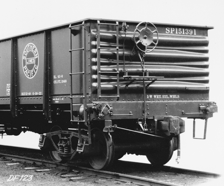
Are they very different? They had many similarities. All were Enterprise Railway Equipment Company designs, with respect to their drop doors and door operating mechanisms. They had the same underframe design and the same composite sides. Indeed, at a glance they look essentially identical. But they are not, because the ends were different. The familiar models of Class G-50-23 had the Improved Dreadnaught ends of their era, and look like many other freight cars of that time. But the Class G-50-20 cars had reverse Dreadnaught ends, that is, with the main or large ribs facing inward into the car.
Let me illustrate this difference in car ends with SP’s Class G-50-13, a 48-foot tight-bottom gondola built in SP shops in 1929. First, the exterior of the car end, which is a reverse Dreadnaught (SP photo).
As stated, this end has the major or large ribs facing inward. That is demonstrated by an interior view looking toward the far end of the car, where the inside of the end looks like a Dreadnaught end usually looks from the outside (SP photo).
The reason for reversing the end is that the inside, in this arrangement, is the stiffer of the two possibilities, thus better resists impacts from the load inside.
How much does this matter? I know of a couple of modelers who have simply numbered a few of the Class G-50-23 models with numbers from the G-50-20 series, assuming that few would notice or recognize the ends being slightly wrong.
But a person who wants to really get the models right would prefer to try and find a way produce the correct ends for G-50-20, and add them to one of the G-50-23 kits. And from the right angle, the reverse Dreadnaught ends are very prominent. The photo below, a detail of one taken at Cooper, California in 1948 by an SP photographer (it’s SP image N-1672-15, from the John R. Signor collection) shows this clearly.
The car is being loaded with sugar beets at a Union Sugar Company loader.
Our problem here is that the commercial ends from either Red Caboose or Detail Associates are accurate Improved Dreadnaught ends, and thus have minor ribs between the major ribs, and also are designed to be facing outward. That of course is the correct end for SP Class G-50-23, and is shown well in this Bethlehem Steel photo of an all-steel G-50-22 gondola with that same end:
So how can the correct reverse-Dreadnaught gondola end be produced? Lacking a good, two-sided end of this type, so that both the interior and exterior would look right, I decided to see if I could modify the Improved Dreadnaught ends produced by either Detail Associates or Red Caboose. I chose the Detail Associates end, part no. 6221, for reasons that will become clear later.
I simply used Tamiya putty to fill the narrow valley on top of each rib on the former “inside,” then cleaned up the excess putty with a file. Once this all seemed far enough along, but hard to judge on the black plastic, I applied a light “witness coat” of light gray to assess progress. Shown below is an original Detail Associates end at left, showing what is molded as the inside of the end, while at right is the end as I modified it, to become the outside of the end.
On the other side of the end, the problem is the minor rib running all the way across between the major ribs, as in the prototype photo above of SP 151391. Here, I used a curved file, sometimes called a “riffler” file, to file away the offending minor rib. This went surprisingly easily, and again, with a “witness coat,” it can be compared to the Detail Associates original at left. The new appearance is most easily seen at the right edge of the gray end:
With the modification technique seeming to work, I now need to modify the second end, add the A and B end details, and paint. Then I can join the assembly process of the rest of the kit. But I will describe all that in a future post.
Tony Thompson
But all three of the versions just mentioned are all the same class, SP’s G-50-23. This is a quite reasonable choice to model; there were 1000 cars in this class, built by General American in 1949 and numbered 150000–150999. Nothing wrong with this class. But the previous year, Pressed Steel Car Company built an even bigger class, Class G-50-20, numbering 1500 cars (cars 56330–57829). There have been no models of this class.
Are they very different? They had many similarities. All were Enterprise Railway Equipment Company designs, with respect to their drop doors and door operating mechanisms. They had the same underframe design and the same composite sides. Indeed, at a glance they look essentially identical. But they are not, because the ends were different. The familiar models of Class G-50-23 had the Improved Dreadnaught ends of their era, and look like many other freight cars of that time. But the Class G-50-20 cars had reverse Dreadnaught ends, that is, with the main or large ribs facing inward into the car.
Let me illustrate this difference in car ends with SP’s Class G-50-13, a 48-foot tight-bottom gondola built in SP shops in 1929. First, the exterior of the car end, which is a reverse Dreadnaught (SP photo).
As stated, this end has the major or large ribs facing inward. That is demonstrated by an interior view looking toward the far end of the car, where the inside of the end looks like a Dreadnaught end usually looks from the outside (SP photo).
The reason for reversing the end is that the inside, in this arrangement, is the stiffer of the two possibilities, thus better resists impacts from the load inside.
How much does this matter? I know of a couple of modelers who have simply numbered a few of the Class G-50-23 models with numbers from the G-50-20 series, assuming that few would notice or recognize the ends being slightly wrong.
But a person who wants to really get the models right would prefer to try and find a way produce the correct ends for G-50-20, and add them to one of the G-50-23 kits. And from the right angle, the reverse Dreadnaught ends are very prominent. The photo below, a detail of one taken at Cooper, California in 1948 by an SP photographer (it’s SP image N-1672-15, from the John R. Signor collection) shows this clearly.
The car is being loaded with sugar beets at a Union Sugar Company loader.
Our problem here is that the commercial ends from either Red Caboose or Detail Associates are accurate Improved Dreadnaught ends, and thus have minor ribs between the major ribs, and also are designed to be facing outward. That of course is the correct end for SP Class G-50-23, and is shown well in this Bethlehem Steel photo of an all-steel G-50-22 gondola with that same end:
So how can the correct reverse-Dreadnaught gondola end be produced? Lacking a good, two-sided end of this type, so that both the interior and exterior would look right, I decided to see if I could modify the Improved Dreadnaught ends produced by either Detail Associates or Red Caboose. I chose the Detail Associates end, part no. 6221, for reasons that will become clear later.
I simply used Tamiya putty to fill the narrow valley on top of each rib on the former “inside,” then cleaned up the excess putty with a file. Once this all seemed far enough along, but hard to judge on the black plastic, I applied a light “witness coat” of light gray to assess progress. Shown below is an original Detail Associates end at left, showing what is molded as the inside of the end, while at right is the end as I modified it, to become the outside of the end.
On the other side of the end, the problem is the minor rib running all the way across between the major ribs, as in the prototype photo above of SP 151391. Here, I used a curved file, sometimes called a “riffler” file, to file away the offending minor rib. This went surprisingly easily, and again, with a “witness coat,” it can be compared to the Detail Associates original at left. The new appearance is most easily seen at the right edge of the gray end:
With the modification technique seeming to work, I now need to modify the second end, add the A and B end details, and paint. Then I can join the assembly process of the rest of the kit. But I will describe all that in a future post.
Tony Thompson
Thursday, June 6, 2019
Choosing new cars for your fleet
This topic probably sounds like the series of posts I have written over the years, about what a car fleet should contain. The most recent of these summarized some of the principles I apply to this problem, for car fleets as a whole, and it can be found here: https://modelingthesp.blogspot.com/2019/05/more-on-choosing-car-fleet.html . But that is not today’s topic.
Instead, I am responding to an interesting question I received by email. It asked, essentially, “when a new freight car comes out, how do you decide if you can use it, and which road name(s)?” This of course touches on the previous posts about overall car fleets, but not directly. So I thought a little about how I have in fact made decisions of this kind. (And I won’t include impulse or “gotta have one” decisions . . .)
I will use as an illustration, the just-out announcement by Rapido Trains that they will be producing an HO scale USRA (United States Railroad Administration) box car, of 40-ton, double-sheathed design. Like the other USRA cars, this car was designed by a high-level committee of experienced railroad mechanical people, and was certainly a successful and durable box car. There were almost 25,000 of them produced, eventually allocated to some 21 railroads and their subsidiaries.
This wide range of prototype owners of the car means it’s a terrific choice for Rapido to produce, and we know they make excellent products. (To see their announcement, you can visit this page: https://www.rapidotrains.com/products/ho-scale/freight-cars/ho-scale-usra-double-sheathed-wood-boxcar .) Of course, the model is hardly a novelty. Good versions of this box car have been available in resin for years from Westerfield and Funaro & Camerlengo, and Accurail makes a quite decent styrene version. Even the much-mocked Ertl styrene USRA box car was a decent starting point for upgrading or redetailing.
But let’s examine the options presented by Rapido. Below is a photo of one of the prototype sample cars, produced in 1918 at the beginning of USRA manufacturing by American Car & Foundry, clearly showing the 5-5-5 corrugated steel end and Andrews trucks, as well as general car appearance (AC&F photo).
Now the question is, can I use one (or more) of the Rapido models? This depends on several factors, in my mind. First, I want to look at the railroads for which Rapido will letter the cars, and see if those are railroads for which I could use additional cars (that goes back to the general car fleet approach mentioned in the first paragraph, top). Second, I want to look at how many USRA 40-ton box cars those railroads received, to see if the number amounts to a credible choice. The Kansas City Southern, for example, only received 100 of these cars, thus statistically not too visible.
And third, this being a World War I-era design, how well did the cars survive on any railroad I would be interested in? An example might be Wabash, which originally got 3000 of these cars, but by 1953, only 54 cars remained. (My modeling year is 1953.) That wouldn’t be a good choice, for the same statistical reason mentioned in connection with KCS.
But where am I getting this information? First, I rely on James E. Lane’s excellent article on all the USRA cars, published in Railroad History (the journal of the Railway and Locomotive Historical Society) in issue 128, back in 1973. You can find this publication used from on-line booksellers. Lane tabulates all the final allocations of each USRA car type, including of course the 40-ton box cars, and the railroad number series for each.
Second, I turn to my copy of the January 1953 issue of the Official Railway Equipment Register or ORER (an NMRA reprint), which is also readily available used. Since Lane provides the number series of the USRA cars on each railroad, one merely has to consult the ORER and see how many were still around by the time I model. As an example, in contrast to my Wabash example above, is the Rock Island, originally the recipient of 2500 cars, and with 773 still in service by 1953.
And third, there is a magisterial article by Pat Wider, published in Railway Prototype Cyclopedia (RPC) volume 16 in 2007, that contains not only roster information but numerous large-format photos of the cars of practically all recipients of these cars. (Incidentally, Mr. Wider followed up with an equally extensive and complete article about the steel rebuilds of these USRA cars in RPC 24.)
It’s logical that the poorer railroads (like Rock Island) would be more likely to hang onto an older box car like this would be in 1953, neither rebuilding it to more modern standards nor scrapping it. Also logical is that any railroad fond of wooden box cars might keep them a long time, too. So Great Northern, originally allocated 1500 cars, still had 1222 of them in service in 1953.
On the other hand, large recipients Santa Fe and Pere Marquette had none of these cars still in service (in original form) after World War II. The Santa Fe, with originally 2700 cars in their class Bx-2, had rebuilt all of the surviving ones into steel-sheathed cars by 1942. Another example would be the St. Louis–San Francisco, the post-WW II survivors of whose 3500-car allocation had also been rebuilt with steel sides.
So my leanings at this point are toward Rock Island, for which I could use another car, and Great Northern, for which I don’t really need more cars, but one would certainly fit.
There’s a third example that is tempting, namely that Rapido will offer two paint schemes of the Toronto, Hamilton and Buffalo (TH&B), which did indeed receive 300 second-hand USRA 40-ton box cars in 1941 from the New York Central (NYC was a half-owner of TH&B). Of the 300 cars, 253 were still listed in the 1953 ORER. The problem there is that Canadian cars seem to have operated in the U.S. in fairly small fractions of their total Canadian fleet size, ten percent in one estimate.
So to sum up, my approach to new freight car offerings is that I would examine any new model on the basis of the railroads (and paint schemes) offered, in terms of my existing car fleet, along with how many of the particular car were still in service on that railroad in my modeling year of 1953. There are ample resources around to make these kinds of determinations, I enjoy using them, and I don’t hesitate to dig into them to help me make decisions.
Tony Thompson
Instead, I am responding to an interesting question I received by email. It asked, essentially, “when a new freight car comes out, how do you decide if you can use it, and which road name(s)?” This of course touches on the previous posts about overall car fleets, but not directly. So I thought a little about how I have in fact made decisions of this kind. (And I won’t include impulse or “gotta have one” decisions . . .)
I will use as an illustration, the just-out announcement by Rapido Trains that they will be producing an HO scale USRA (United States Railroad Administration) box car, of 40-ton, double-sheathed design. Like the other USRA cars, this car was designed by a high-level committee of experienced railroad mechanical people, and was certainly a successful and durable box car. There were almost 25,000 of them produced, eventually allocated to some 21 railroads and their subsidiaries.
This wide range of prototype owners of the car means it’s a terrific choice for Rapido to produce, and we know they make excellent products. (To see their announcement, you can visit this page: https://www.rapidotrains.com/products/ho-scale/freight-cars/ho-scale-usra-double-sheathed-wood-boxcar .) Of course, the model is hardly a novelty. Good versions of this box car have been available in resin for years from Westerfield and Funaro & Camerlengo, and Accurail makes a quite decent styrene version. Even the much-mocked Ertl styrene USRA box car was a decent starting point for upgrading or redetailing.
But let’s examine the options presented by Rapido. Below is a photo of one of the prototype sample cars, produced in 1918 at the beginning of USRA manufacturing by American Car & Foundry, clearly showing the 5-5-5 corrugated steel end and Andrews trucks, as well as general car appearance (AC&F photo).
Now the question is, can I use one (or more) of the Rapido models? This depends on several factors, in my mind. First, I want to look at the railroads for which Rapido will letter the cars, and see if those are railroads for which I could use additional cars (that goes back to the general car fleet approach mentioned in the first paragraph, top). Second, I want to look at how many USRA 40-ton box cars those railroads received, to see if the number amounts to a credible choice. The Kansas City Southern, for example, only received 100 of these cars, thus statistically not too visible.
And third, this being a World War I-era design, how well did the cars survive on any railroad I would be interested in? An example might be Wabash, which originally got 3000 of these cars, but by 1953, only 54 cars remained. (My modeling year is 1953.) That wouldn’t be a good choice, for the same statistical reason mentioned in connection with KCS.
But where am I getting this information? First, I rely on James E. Lane’s excellent article on all the USRA cars, published in Railroad History (the journal of the Railway and Locomotive Historical Society) in issue 128, back in 1973. You can find this publication used from on-line booksellers. Lane tabulates all the final allocations of each USRA car type, including of course the 40-ton box cars, and the railroad number series for each.
Second, I turn to my copy of the January 1953 issue of the Official Railway Equipment Register or ORER (an NMRA reprint), which is also readily available used. Since Lane provides the number series of the USRA cars on each railroad, one merely has to consult the ORER and see how many were still around by the time I model. As an example, in contrast to my Wabash example above, is the Rock Island, originally the recipient of 2500 cars, and with 773 still in service by 1953.
And third, there is a magisterial article by Pat Wider, published in Railway Prototype Cyclopedia (RPC) volume 16 in 2007, that contains not only roster information but numerous large-format photos of the cars of practically all recipients of these cars. (Incidentally, Mr. Wider followed up with an equally extensive and complete article about the steel rebuilds of these USRA cars in RPC 24.)
It’s logical that the poorer railroads (like Rock Island) would be more likely to hang onto an older box car like this would be in 1953, neither rebuilding it to more modern standards nor scrapping it. Also logical is that any railroad fond of wooden box cars might keep them a long time, too. So Great Northern, originally allocated 1500 cars, still had 1222 of them in service in 1953.
On the other hand, large recipients Santa Fe and Pere Marquette had none of these cars still in service (in original form) after World War II. The Santa Fe, with originally 2700 cars in their class Bx-2, had rebuilt all of the surviving ones into steel-sheathed cars by 1942. Another example would be the St. Louis–San Francisco, the post-WW II survivors of whose 3500-car allocation had also been rebuilt with steel sides.
So my leanings at this point are toward Rock Island, for which I could use another car, and Great Northern, for which I don’t really need more cars, but one would certainly fit.
There’s a third example that is tempting, namely that Rapido will offer two paint schemes of the Toronto, Hamilton and Buffalo (TH&B), which did indeed receive 300 second-hand USRA 40-ton box cars in 1941 from the New York Central (NYC was a half-owner of TH&B). Of the 300 cars, 253 were still listed in the 1953 ORER. The problem there is that Canadian cars seem to have operated in the U.S. in fairly small fractions of their total Canadian fleet size, ten percent in one estimate.
So to sum up, my approach to new freight car offerings is that I would examine any new model on the basis of the railroads (and paint schemes) offered, in terms of my existing car fleet, along with how many of the particular car were still in service on that railroad in my modeling year of 1953. There are ample resources around to make these kinds of determinations, I enjoy using them, and I don’t hesitate to dig into them to help me make decisions.
Tony Thompson
Monday, June 3, 2019
Rolling stock upkeep
Upkeep? Isn’t a rolling stock model, once completed and in service, all set to operate for quite a while? Can we not apply the immortal comment, “what could go wrong?”
I have written in earlier posts about what I called a “rookie test,” meaning that a piece of rolling stock that had not been in service before, or was newly maintained in some way, needed thorough testing before entering service. Otherwise, such issues as truck swing, coupler swing, coupler height, coupler knuckle spring operation, and so on, could come back and bite you. That post can be found at this link: https://modelingthesp.blogspot.com/2018/07/the-rookie-test.html .
I followed up awhile later with commentary on how rigorous this kind of test needed to be, in a post entitled “Lessons learned,” which is available at: https://modelingthesp.blogspot.com/2018/09/lessons-learned.html . In fact, re-reading that post now makes me realize that the term “rookie test,” though entirely appropriate for cars entering service, is misleading in that it seems to imply that only the new rolling stock presents problems. As that second post, just cited above, states, the same standards may need to be applied to cars already in service.
One sign of that, as an ongoing process that I have had to recognize, can be found in the post I wrote recently about correcting problems with the friction-fit coupler box lid on Athearn tank cars. That post is here: https://modelingthesp.blogspot.com/2019/05/fixing-athearn-tank-car-coupler-pockets.html . There are plenty of other examples that have emerged in my ongoing maintenance tasks at the workbench.
Here’s one instance: I continue to search out and replace non-Kadee couplers on my rolling stock. I don’t mean to imply that only Kadees can do the job, only that I have come to believe that having all one kind of coupler does make a difference in reliability and consistent coupling and coupled-up train continuity. I find the knock-off Kadee copies that are added to some Chinese-manufactured cars especially annoying, as they look very much like a real Kadee (though usually very shiny, which Kadees are not), and simply do not perform as well as the design they are copied from.
Now let me say a few words about a topic familiar to many modelers: Kadee no. 5 vs. no. 58. The photo below shows one of each, happily coupled and working fine.
I should explain that I continue to hear the idea that Kadee no. 5 and no. 58 couplers do not work well together. My experience is that this claim is entirely untrue. I have lots of both types on my layout, and they are generally just fine. Why do I qualify that words “just fine” with “generally”? The no. 58 does have some limitations compared to the no. 5. It does not have the overall height (in elevation view), so is less forgiving on vertical curves, and less tolerant of coupler height mismatch with adjoining cars. It is smaller, and in particular has less “gather” (in plan view), so is less capable for coupling on sharp curves (actually a prototypical feature).
But these issues are not because there is any mismatch between no. 5 and no. 58, only that the two are different. If you are used to how no. 5s behave in model operation, you will certainly find that no. 58s are different, usually in a less convenient way. But let me repeat: in my experience, the two coupler types work just fine together, whether in train service or in switching, even if it is true that the no. 58 does not offer all the operating convenience of the no. 5. For me, that is more than balanced by the better appearance of the smaller no. 58.
One thing I now often do as part of a “rookie test” or “return-to-service test” is to couple up a string of some cars that have been worked on, and use a locomotive to run them back and forth through a sequence of the diverging sides of No. 5 turnouts, at slow speed and then at faster speeds, to see if they behave. And when that test goes all right, I rearrange their order and repeat, and maybe create a third ordering of the cars and repeat again.
I should observe that even this testing is not always sufficient, because coupling a particular car to some other car may bring a whole new problem into view. But this test is a good starting point.
I am occasionally asked my view on the Accumate couplers from Accurail. When these were first introduced, I bought five pairs and installed them on five freight cars, each from a different manufacturer, and then operated them intensively in switching and in train service. I operated them all together, and then operated them all in mixtures with Kadee no. 5 and no. 58 couplers. My conclusions? Operated together, Accumates are just fine, and are small enough to look good. Operated with Kadees? Just not nearly as dependable. I suspect that an entire car fleet equipped with Accumates would be fine, but I don’t want them mixed in with Kadees. As I said, I have chosen the latter.
One other maintenance task that keeps on happening: I find myself replacing the plastic sill steps on some models. Though I often replace such steps with A-Line metal sill steps before the cars even enter service, I don’t always get to it before wanting to use the cars in an operating session. But inevitably those plastic steps start to break off, and then the car ends up back on the workbench, to receive the A-Line steps. To do this, I usually have to add some blocking behind the side sill, to make a sturdier platform to drill for sill steps. (I have shown this method in use in several blogs, for example this one: https://modelingthesp.blogspot.com/2011/12/modeling-project-m-box-car.html .)
And of course there are always the maintenance tasks of replacement of missing or broken grab irons, brake wheels, and other parts. I don’t really feel bothered by this, because if a layout is operated, some things are going to get damaged. That’s just a fact of nature. So, because I do want to have guests operate the layout, occasional damage is not only predictable but unavoidable. I just fix it and move on.
Tony Thompson
I have written in earlier posts about what I called a “rookie test,” meaning that a piece of rolling stock that had not been in service before, or was newly maintained in some way, needed thorough testing before entering service. Otherwise, such issues as truck swing, coupler swing, coupler height, coupler knuckle spring operation, and so on, could come back and bite you. That post can be found at this link: https://modelingthesp.blogspot.com/2018/07/the-rookie-test.html .
I followed up awhile later with commentary on how rigorous this kind of test needed to be, in a post entitled “Lessons learned,” which is available at: https://modelingthesp.blogspot.com/2018/09/lessons-learned.html . In fact, re-reading that post now makes me realize that the term “rookie test,” though entirely appropriate for cars entering service, is misleading in that it seems to imply that only the new rolling stock presents problems. As that second post, just cited above, states, the same standards may need to be applied to cars already in service.
One sign of that, as an ongoing process that I have had to recognize, can be found in the post I wrote recently about correcting problems with the friction-fit coupler box lid on Athearn tank cars. That post is here: https://modelingthesp.blogspot.com/2019/05/fixing-athearn-tank-car-coupler-pockets.html . There are plenty of other examples that have emerged in my ongoing maintenance tasks at the workbench.
Here’s one instance: I continue to search out and replace non-Kadee couplers on my rolling stock. I don’t mean to imply that only Kadees can do the job, only that I have come to believe that having all one kind of coupler does make a difference in reliability and consistent coupling and coupled-up train continuity. I find the knock-off Kadee copies that are added to some Chinese-manufactured cars especially annoying, as they look very much like a real Kadee (though usually very shiny, which Kadees are not), and simply do not perform as well as the design they are copied from.
Now let me say a few words about a topic familiar to many modelers: Kadee no. 5 vs. no. 58. The photo below shows one of each, happily coupled and working fine.
I should explain that I continue to hear the idea that Kadee no. 5 and no. 58 couplers do not work well together. My experience is that this claim is entirely untrue. I have lots of both types on my layout, and they are generally just fine. Why do I qualify that words “just fine” with “generally”? The no. 58 does have some limitations compared to the no. 5. It does not have the overall height (in elevation view), so is less forgiving on vertical curves, and less tolerant of coupler height mismatch with adjoining cars. It is smaller, and in particular has less “gather” (in plan view), so is less capable for coupling on sharp curves (actually a prototypical feature).
But these issues are not because there is any mismatch between no. 5 and no. 58, only that the two are different. If you are used to how no. 5s behave in model operation, you will certainly find that no. 58s are different, usually in a less convenient way. But let me repeat: in my experience, the two coupler types work just fine together, whether in train service or in switching, even if it is true that the no. 58 does not offer all the operating convenience of the no. 5. For me, that is more than balanced by the better appearance of the smaller no. 58.
One thing I now often do as part of a “rookie test” or “return-to-service test” is to couple up a string of some cars that have been worked on, and use a locomotive to run them back and forth through a sequence of the diverging sides of No. 5 turnouts, at slow speed and then at faster speeds, to see if they behave. And when that test goes all right, I rearrange their order and repeat, and maybe create a third ordering of the cars and repeat again.
I should observe that even this testing is not always sufficient, because coupling a particular car to some other car may bring a whole new problem into view. But this test is a good starting point.
I am occasionally asked my view on the Accumate couplers from Accurail. When these were first introduced, I bought five pairs and installed them on five freight cars, each from a different manufacturer, and then operated them intensively in switching and in train service. I operated them all together, and then operated them all in mixtures with Kadee no. 5 and no. 58 couplers. My conclusions? Operated together, Accumates are just fine, and are small enough to look good. Operated with Kadees? Just not nearly as dependable. I suspect that an entire car fleet equipped with Accumates would be fine, but I don’t want them mixed in with Kadees. As I said, I have chosen the latter.
One other maintenance task that keeps on happening: I find myself replacing the plastic sill steps on some models. Though I often replace such steps with A-Line metal sill steps before the cars even enter service, I don’t always get to it before wanting to use the cars in an operating session. But inevitably those plastic steps start to break off, and then the car ends up back on the workbench, to receive the A-Line steps. To do this, I usually have to add some blocking behind the side sill, to make a sturdier platform to drill for sill steps. (I have shown this method in use in several blogs, for example this one: https://modelingthesp.blogspot.com/2011/12/modeling-project-m-box-car.html .)
And of course there are always the maintenance tasks of replacement of missing or broken grab irons, brake wheels, and other parts. I don’t really feel bothered by this, because if a layout is operated, some things are going to get damaged. That’s just a fact of nature. So, because I do want to have guests operate the layout, occasional damage is not only predictable but unavoidable. I just fix it and move on.
Tony Thompson
Subscribe to:
Posts (Atom)