Wednesday, August 31, 2022

PFE Class R-30-24 plywood reefer, Part 5

This series of posts describes building a plywood-sheathed refrigerator car, PFE Class R-30-24, from a collection of parts, most of them from Sunshine masters, given to me by Frank Hodina, and the balance provided by Terry Wegmann. Most assembly is now complete; in the previous post (see it at: https://modelingthesp.blogspot.com/2022/08/pfe-class-r-30-24-plywood-car-part-4.html ), I showed the assembled and lettered car body with most of its details attached. 

Perhaps I should repeat the prototype information: in late 1947, PFE embarked on its last large rebuilding project, converting a few thousand Class R-30-12 and -13 cars (all that remained at that time) to a new class, R-30-24 (or R-40-24, if an occasional R-40-2 car was rebuilt). Notably, these were plywood-sheathed, something PFE had experimented with earlier. For more background and a prototype photo, see the first post in this series: https://modelingthesp.blogspot.com/2020/04/building-pfe-class-r-40-24-car.html .

In the previous post, cited in the top paragraph, above, I mentioned that the model’s car body had been attached to the underbody. That meant it was time to add the corner sill steps. I used the A-Line “Style A” steps, installed with canopy glue. These are very similar to the PFE style. Here is the model at this point, with those steps unpainted.

My box of parts included some super brass parts for the two-rung steps for under the door. I am not certain who made them originally (I am reliably informed that it was Terry Wegmann), but they are great looking, have nice attachment pins, and are sturdy.

I attached these steps with canopy glue, along with the fan control boxes on the side sill near the fan shaft hub.

Last, I attached an etched metal running board, and ice hatch latch bars, all with canopy glue. I had to hand-bend roof corner grabs to match the roof mounting holes, for which I used 0.015-inch brass wire, and attached them with canopy glue. As the car photo above is of the left side, I show the right side below.

I could now proceed with weathering. This car would be 5 or more years old by the time I model, in 1953, and it has the original paint scheme that it received when rebuilt. But as experienced modelers know, age alone is not a guide to the state of weathering on PFE cars, becuase they were frequently washed until about 1953 or 1954. Naturally one can only guess how many times a car may have been washed since going into service. 

Given that uncertainty, I decided on moderate weathering only. Once the car was weathered and that coat protected by flat finish, I added reweigh decals, route cards, and chalk marks. (All those points of detail have been covered in prior posts, and you could use any of those terms in the search box at the top right of this post to find them.)

With that, this car was ready to enter service on the layout, and I show it below, spotted at Coastal Citrus, a lemon shipper, in my layout town of Santa Rosalia. You can compare its appearance to the next photo above, which was taken prior to weathering and finishing. PFE orange did indeed fade toward a more yellow color, as I’ve tried to do here.

This was a fun build, one I had been looking forward to, and marks completion of one of the two plywood car projects on my bench. Still working through the stash, in a sense.

Tony Thompson

Sunday, August 28, 2022

Operating on a fine N-scale layout

 I had the good fortune last week to participate in an operating session on one of the area’s nicest N-scale layouts, Steve Van Meter's recreation of the early 1950s SP and WP in the Bay Area. With Steve’s permission, I want to show some indications of the quality of this layout. But first, one of those traditional overviews of much of the crew:

At right is John Sutkus, Oakland yardmaster, and at left, facing the camera, is Mike Stewart, Tracy yardmaster. Others in the distance are forming one of those often-seen congestion clumps at a busy part of the layout.

Around the layout, the backdrop skylines are all fairly indistinct, no details, which I personally think is a very nice way to keep attention on the foreground. Here is an example (the train happens to be the Tracy Turn I operated, returning to Oakland).

Steve has endeavored to reproduce the “feel” of the region and the era, while creating several nice switching areas and considerable mainline running. One of the well-done packing-house areas is shown below, containing altogether four packing houses, an interesting and time-consuming switching challenge. The packing houses are in the distance, the mainline is in the foreground. Both fruit trees, at left, and wine grapes, at right, are included here.

Another nice re-creation is the curved Del Monte canning plant (parts of which survive) in Alameda, shown here much like it was at one time. The nearby U.S. Steel distribution facility is below. This is the area served by the Alameda Belt Line.

Another photo will show an example of the many nice touches that abound on the layout. This represents a loading facility for piggyback trailers, where a new installation has been made atop an older yard area. The asphalt paving, over the original brick pavement, has worn through in places. I thought this was really a nice representation of something rarely modeled.

Of course, things can go wrong in operating sessions. Shown below is an example, with Clif Linton holding the throttle with which he has just stringlined an entire piggyback train. (I think the grin is embarrassment, not triumph.) No harm done, all cars were quickly re-railed. This is the kind of thing that makes layout owners pull their hair out (ask me how I know), but in reality are taken in stride by most operators, who, after all, have dealt with lots of problems before.

This was a very pleasant session, the first since the pandemic on this layout, even though some issues understandably arose — and were dealt with. Quite a nice layout, and fun to operate.

Tony Thompson

Thursday, August 25, 2022

Layout origins, Part 2

 In the previous post on this topic, I showed photos from the 1980s of the earliest work in constructing my layout town of Ballard, concluding with what it looked like when the layout was dismantled for moving to California. You can read that post here: https://modelingthesp.blogspot.com/2022/06/more-on-layout-origins.html

I should also repeat that the track arrangement in Ballard was designed, from the beginning, as a virtual copy of Terry Walsh’s layout town of West Agony (see specifics here: https://modelingthesp.blogspot.com/2018/06/my-ballard-track-arrangement.html ), because of its versatility as a switching location.

Below is one of the photos that didn’t make it into my cover story in the June 1990 issue of Railroad Model Craftsman, showing a freight train of the Lompoc & Cuyama (as the railroad was then known) approaching the Ballard depot. The two industries just above the locomotive are still located in Ballard, but not in this location. The large hill at left would be partly demolished in the move, and later replaced.

The layout parts that were saved from Pittsburgh were in storage in a couple of places, from 1994 until we moved into a second house in Berkeley in 2005, a house that had room for the layout. As the layout was being re-assembled, the Ballard track board (3/4-inch plywood) was simply on edge alongside the layout. Even now, this photo startles me a little.

As I showed in an earlier post, having built my staging transfer table, Ballard could be put in place (see: http://modelingthesp.blogspot.com/2011/09/ballard-2.html ). Here is a photo of my staging as it was built, before Ballard was placed on top of it. Notice the limited extent of the backdrop, also salvaged from the Pittsburgh layout.

With the help of my son Cam, we lifted the Ballard track board and placed it onto new supports above the staging. Here you see it about to be put in place. My wife took the photo.

Of course there were no buildings in place, as I rarely glue a structure to the layout. All had been removed and carefully packed for moving when we left Pittsburgh. Below is a view into the Ballard scene right after placing the track board, with two of the salvaged building simply set in place. (Both needed repair). Also note the gap at the bottom of the backdrop. This was to prove a challenge.

This was a somewhat discouraging time, seeing how much needed to be repaired, and I had to also re-connect the track leading from the mainline level up to Ballard. Below you see that project being completed. A few more of the Ballard structures, and a few freight cars, have been set in place, but extensive scenery repair was also going to be needed.

What I’m not showing directly here is the state of the large hill at the end of the layout (see top photo in this post). This had been sliced off to permit moving the end section of the layout, and now had to be entirely recreated. I will summarize all that in a future post.

Tony Thompson

Monday, August 22, 2022

Replacing a fast clock

 Some time ago, I decided that my layout operations could benefit by using a fast clock, because that would open the door for effective use of a timetable based on the Southern Pacific prototype, during operating sessions. My ruminations on that topic were summarized in a post about five years ago (you can see it at: https://modelingthesp.blogspot.com/2017/12/fast-clocks.html ).

In the post just cited, I mentioned that I liked the features of the GML Enterprises system, and some months later, did indeed go ahead and purchase that set-up for a fast clock. That too was described in a follow-up post (here is a link: https://modelingthesp.blogspot.com/2018/05/fast-clocks-part-2.html ). Here’s how the main clock looks in place:

Since that time, layout operating sessions have worked well with the clock at a 1:1 time ratio (ordinary time rate). I did experiment with a 2:1 ratio, but for a switching-dominated layout like mine, it really was best to use 1:1. The first session with the new clock was described in a post (you can read it here: https://modelingthesp.blogspot.com/2018/05/an-operating-session-with-clock-and.html ).

Then came the pandemic. Like practically all layout owner, I didn’t host operating sessions for almost two years, except for my granddaughter. The clock was operated occasionally, but not often. Then in preparation for my operating session in June, the clock wouldn’t run. Voltage was not getting to the clock unit from the clock control panel.

I naturally thought first about contacting the maker, but the GML company (named for its principal, Gene M. Lewis), is out of business; Mr. Lewis has passed away. I’ve tried trouble-shooting the controls and wiring, but nothing has worked. I am evidently out of luck, not being an electronics person who could dig into the circuit boards to find a fault.

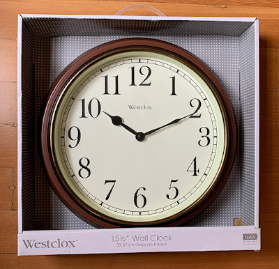
Of course, now that I know that my preferred clock rate is 1:1, I don’t really need a “controllable” clock, but can replace the GML with any regular clock. And they can be found at almost any hardware store, often for prices in the $20 range. So I went out and bought one, shown below as it comes from the store. Most clocks are packaged this way, so you can clearly see what you would get. I chose a fairly classical look for my 1953 layout.

The idea for using such a clock is to take the battery out of the clock until needed for an op session. Then in preparation for a session, take down the clock, and set for the desired time of day to start the session. As soon as the session begins, inset battery and re-hang clock. I will be trying that process in an upcoming session, likely in September.

So with a chance to choose a new clock location, I thought it ought to be somewhat toward the Shumala side of the layout (it’s mostly used by the crew working on that side), but still visible on both sides. Here is how it looks when in place (already set for one of the starting times I use).

I suppose there’s no “moral” to this story, except that you may not need a variable-speed clock if you know you want to operate at 1:1, as I do. And plain clocks like the one I bought are inexpensive and easy to use.

Tony Thompson

Friday, August 19, 2022

A UP automobile car, Part 2

This post continues an account of building a Proto2000 kit for a Union Pacific 50-foot automobile car, particularly the changes needed to the model that are not contained in the kit directions. You can read that post here: https://modelingthesp.blogspot.com/2022/04/adding-up-automobile-car.html .

Meanwhile, I did my usual procedure, drilling and tapping the underbody to accept 2-56 screws for both the trucks and the coupler box. And the rather poor Proto2000 coupler box was discarded in favor of a Kadee box to house the No. 58 coupler.  The wheelsets have the “fat” wheel treads, but since this is essentially a “mainline” car, they won’t be particularly visible on the layout.

Next, I began adding details to the car side: doors and ladders. But before going too far, I needed to face a complication: the UP cars had the door track extend across the tabs I’d already made (in the prototype photo in the previous post, link in the first paragraph above, look at the side sill profile to the left of the double doors). After experimenting with ways to make this fiddly detail, I decided not to worry about including it. Again, it’s going to be a “mainline” car.

Beyond that issue, details were attached entirely by kit direction, until I came to the running board. I decided to use one of the beautiful Kadee 50-foot grid running boards. This class of cars was not built with that type of running board, but after World War II, Union Pacific was active in upgrading running boards to steel grid types, usually Apex like the Kadee part. One welcome feature of these boards is that they already have very nice corner grab irons installed. I attached the running board with canopy glue.

In the photo above, it’s obvious that the sill steps haven’t been added, just waiting until the underbody was mated to the car shell. That prevents the sill steps from being the “outermost” car parts during installation. Though good-looking, these are very thin and thus fragile parts, and I fully expect to be replacing them with A-Line metal steps after a few operating sessions.

Another issue is route card boards. On this class of UP box cars, they were installed on the bolster end at the left of each car side (you can see them in the prototype photo in the post cited in the first paragraph, above). I used a small styrene strip to represent these. Once the route card boards installed and painted, and the steps were installed, I gave the entire model a coat of flat finish, preparatory to weathering.

My weathering method, using acrylic washes is well described in the “Reference pages” that have links provided at the top right corner of this blog post, for anyone desiring more information. For this model, my first decision was to indicate some paint failure on the roof, a common occurrence with galvanized roof panels, to which paint did not stick well. 

Prototype photos show that paint failure on galvanized roofs begins at sharp edges, such as raised panel edges and roof ribs, then spreads. I have tried to reproduce that. I brush-painted Tamiya “Light Sea Gray” (no. XF-25) in irregular patches, inspired by various prototype images. Below is a roof shot, showing how this “paint failure” representation looks, after weathering.

Below is shown the same side of the model that you saw above, after weathering, and addition of reweigh and repack stencils, along with some chalk marks. As the paint scheme would be some years old in my modeling year of 1953, the car is moderately dirty.

This will fill out my fleet of automobile cars nicely, cars that I operate on the layout in through trains between Los Angeles and the Bay Area (loaded one way, empty the other). It will probably show up in the next operating session!

Tony Thompson

Tuesday, August 16, 2022

The Central Vermont in Northern California

 Many people reading this blog have likely heard of this ambitious HO scale layout being built under Paul Weiss’s direction in Novato, California. I won’t try to provide a layout description, as there is a well-populated website available with ample information and many photos (that website is here: https://www.cvrailroad.com/ ). 

In brief, the layout models the Central Vermont in 1956, the southern end of the railroad  between East New London, Connecticut, and Palmer, Massachusetts. Like many layouts, this one had a long pandemic layoff, but it came back to life last weekend with a large crew. As we all saw, layout building had actually advanced greatly during the pandemic, with many buildings added and much scenery moved forward. 

I’ll just show a single example (there are many more on the site linked in the first paragraph above). One town along the CV is South Coventry, which had a classic brick depot (prototype photo below from the layout website, obviously a magazine or book spread). 

Here is the model version as it now appears, obviously a middle deck of three at this location on the layout. But it’s not modeled with snow on the ground <grin>.

An interesting aspect of the layout is that it is entirely built on a raised platform, permitting agent’s offices and the East New London yardmaster and clerk’s offices to be underneath, with a layout-floor-level window into the layout. My assignment was as that yardmaster. Below is a typical view from my office. 

Perhaps this photo shows why I usually was up at layout level, supervising yard work where I could see it. But the space had its use. Note the signal control at left in the photo. This controls the yard entrance signal 25 feet away at the yard limit, and the small video screen above it is a live feed of the area right at the signal, so the yardmaster has an idea which train is there.

But don’t surmise that I think this “low office” idea is bad. Far from it. For the agents, it really is ideal. They get adequate space to work, use telephones, and hand up orders, without intruding into the layout space itself. Here is one example (Paul Weiss photo), with Dan Obermeyer in the chair at Montville.

Finally, I should show the large East New London yard I was supervising. The nearest person is Ray Lorber, switchman, and beyond him is yard foreman Andy Schnur, who did a great job getting all the work done on schedule.

I guess I should conclude with a photo of the man himself, Paul Weiss, who has not only done a superb job in building the layout and inspiring and supervising his many co-workers, but having the vision of what the layout could be, and the drive to make it happen. 

Thanks again, Paul, for the superb layout (work in progress though it is) and for this excellent operating session.

Tony Thompson

Sunday, August 14, 2022

PFE Class R-30-24 plywood car, Part 4

 In Part 3, I showed the completed body (superstructure) box, and the completed attachment of underframe parts and brake detailing, for this model of a plywood-sheathed PFE car of Class R-30-24. (To see that post, use this link: https://modelingthesp.blogspot.com/2022/07/pfe-class-r-40-24-plywood-car-part-3.html ). Note I have recognized that the old-design underframe on this car makes it a 30-ton car, not a 40-ton car, thus Class R-30-24. Now it was time to detail the body. 

I began by adding grab irons. PFE used simple bolted grab irons on wood-sheathed cars, so I used Westerfield 18-inch brass-wire grab irons for this car, attaching them with CA. I also added the fan shaft hubs and door hinges, black styrene provided among the parts I got. Then it was time to brush-paint the side sills and the door latches black.

Next I attached the side and end ladders. Not all modelers realize that these ladders on the prototype were arranged so that the rungs on both ladders were aligned. You can understand why if you picture a brakeman having to step around the corner, from one ladder to the other. And of course this means that the two ladders must have identical rung spacings.

Below the car body is shown with the above-listed additions and painting, along with the ice hatches. 

Next came completion of the B-end details. As with the ladders and other details, these were attached with canopy glue. Once that was done, I decided to proceed with lettering. For this, I mostly used the outstanding Microscale set 87-501, with Dick Harley’s excellent artwork. But I needed parts of the previous (pre-1946) paint scheme, and used National Car set D182, for PFE Class R-40-14 cars. This yielded the color UP emblems and the words, “ventilated refrigerator.”

For placement of this lettering, it was essential to have on the bench Dick Harley’s superb exposition of PFE painting and lettering, found in the second half of the book, Southern Pacific Freight Car Painting and Lettering Guide (SPH&TS, 2016), by Dick Harley and me. I chose to letter this model in the 1947 paint scheme, likely applicable to the early cars rebuilt to Class R-30-24. It’s shown on page 136.

Here’s the decal application. Note also that the steel kick plate under the door is now black, as it should be on a wood-sheathed PFE car in this era. 

Next I added trucks and couplers to the underframe (for which, see prior post, cited in first paragraph, above), which by now had been painted black. The couplers were my standard Kadee “whisker” type. For trucks, I consulted the PFE equipment diagram for this car class (you can click on the image to enlarge it, if you wish), with trucks listed at lower center:

My car number, PFE 66240, clearly falls into the series 66030–66542, which received Barber S-2 trucks. There is a Tahoe Model Works truck of this kind, TMW 113, a pair of which I applied to this car. I did have to fabricate some thicker washers for the trucks to sit high enough for the couplers to be at correct height. At that point, I inserted the 30-ton underbody component into the car body, with canopy glue on all mating surfaces. 

With the body now attached to the underbody, I was ready to continue adding body details. I will describe work on those aspects in a following post. 

Tony Thompson