Saturday, December 21, 2024

Another Winter Solstice

Once again, it’s the Winter Solstice, the shortest day. And as I have done on a number of past occasions of this day, I want to recognize what it means to me. Below I reprint essentially the post I wrote for this day in 2012. I hope you will find it interesting.

The Shortest Day

One of my vivid memories from childhood is my father relishing this day, which seemed odd to me then, what with the days shortening and the nights closing in, and of course colder and rainier weather. But he always said, “Now the days will be getting longer,” and of course, so they will.

 What hadn’t occurred to me in those days was that humans for many, many centuries have had the same feelings about this day that my dad did, and in more primitive times, for better reasons.

 Ever since my wife and I discovered the performances known as Christmas Revels, we attended a fair number of them here in the Bay Area. Revels was created by John Langstaff in 1957, and the tradition gradually grew and extended over the years. Today Christmas Revels is performed in several cities around the country (for the location of those cities, you can visit their map at this link: https://revels.org/about/#revels-nationwide , and from there go to their home page to learn more about their history and what Revels is.)

 A favorite part of the performance of every Christmas Revels is the reading, toward the end, of a poem by Susan Cooper, written for Revels in 1977 and for me a delight. I reproduce it below, with permission from Cooper, to whom I wrote an email and requested the use. (The poem is all over the Internet, in both written and spoken form, though often mis-punctuated and sometimes with words changed — imagine the nerve!) 

She sent me a copy of it as she wrote it, so that it could be presented correctly. (If you’d like to know more about her, please visit her web site: http://www.thelostland.com/ .) She also mentioned that she was happy to give permission for my use in this blog, as she is descended from three generations of English railwaymen!

THE SHORTEST DAY

By Susan Cooper

So the shortest day came, and the year died,
And everywhere down the centuries of the snow-white world
Came people singing, dancing,
To drive the dark away.
They lighted candles in the winter trees;
They hung their homes with evergreen,
They burned beseeching fires all night long
To keep the year alive.
And when the new year's sunshine blazed awake
They shouted, revelling.
Through all the frosty ages you can hear them
Echoing, behind us -- listen!
All the long echoes sing the same delight
This shortest day
As promise wakens in the sleeping land.
They carol, feast, give thanks,
And dearly love their friends, and hope for peace.
And so do we, here, now,
This year, and every year.
Welcome Yule!

A far more eloquent presentation of our traditions than I could ever have written. I hope you enjoy it as much as I do.

 Tony Thompson

Wednesday, December 18, 2024

The yard brush

I suspect this is another of those titles for a post that will puzzle some readers. What I am referring to is a soft brush provided to a yardmaster or yard operator.  But why, you cry. The answer is simple: when a lull in yard work comes along, the yard operator can remove dust from car roofs or interiors. To illustrate, below is a hopper car interior, quite dusty as the finger marks show. Why not dust this?

I have to quickly mention that in O scale, many layout owners seem to like the dusty look, and will tell you, instead of dusting the cars, to please not touch them and thereby disturb the nice dust. This post is for all other types of layout owners, who generally have the opposite view of dust.

So what kind of brush am I suggesting? The usual sort of “make-up” powder brush, available at any cosmetics counter, is large and soft, perfect for dusting without disturbing detail parts. The best kind is the broad brush I was told is a “blusher” of the kind you see below. This type is also called a “face brush” or a “powder brush.” This brush is about 5 inches long, and is the one I use for my layout.

As you can see, the brand is “essence of Beauty.” They have an extensive line of makeup powders and brushes, and brushes are usually around $5.00 or so.

Another brush I have used, and currently acts as my “traveling brush,” when I operate at someone else’s layout, is from the “bareMinerals” brand, and is also about 5 inches long. I use the larger, soft end. This brand also offers a “powder brush” like the one shown above. Brushes from this brand are considerably more expensive than the “essence of Beauty” brushes; I inherited this one.

I have a third brush, with no brand name on it, very similar physically to the others, which I keep on my workbench (in a different place than the layout). It’s the same size, but has black bristles, equally as soft as the others, and I use it for the same kinds of dusting.

All these brushes are quite effective, and I like what they can do. They all get used, whether home or away. And by the way, of course I ask the layout owner’s permission to dust cars, as should anyone! Below I show my “visiting” brush in action on Jim Providenza’s well-known Santa Cruz Northern layout, though in reality it wasn’t needed, just a demo.

So is this important? No, not really, totally a detail, though I sometimes remark that a well-equipped yard should have a yard brush handy. Brushes like this need not be expensive, so you might give one a try. Whether you permit visiting operators to wield one is a separate decision <grin>.

Tony Thompson

Sunday, December 15, 2024

Modernizing a PFE model

Recently a friend approached me with a model he had recently purchased, a Pacific Fruit Express Class R-40-2 car sold by Fox Valley Models (reportedly the former MTH model product). He had not realized it was a 1920s paint scheme (he models the 1950s) and did recognize that the yellow paint scheme would have been long gone by the time he models.

Here is a photo of the model. It is in some ways nicely done, with wire grab irons, and nice crisp sill steps. It even even has separately applied UP and SP emblems, evidently to represent the porcelain enamel medallions that PFE applied for a few years after 1928 (and then removed to avoid the hazard of them falling off the cars). The outside-metal roof surface being black and wood roof parts boxcar red is correct, as is all the lettering, for a car built in 1928.

Below is a photo of the prototype car class (Steve Peery collection). This photo, and considerable information about the prototype cars, can be found in Chapter 6 of Pacific Fruit Express (2nd edition), Thompson, Church and Jones, Signature Press, 2000.

But in early 1929, PFE changed its car color from yellow (an Armour Yellow, not the lemon yellow on this model) to a light orange. [Eight years later, SP would adopt this color for its new Daylight trains, and it became known as Daylight Orange, though originated in use by PFE.] The entire PFE fleet was entirely orange by the early 1930s, certainly before 1934. So the color of the model would be incorrect for any layout set later than 1934.

I won’t go further into PFE painting history, but an excellent source is available. Extensive information on PFE painting and lettering over time can be found in Southern Pacific Freight Car Painting and Lettering Guide, Dick Harley and Anthony Thompson, SPH&TS, 2016.

The Class R-40-2 design happens to have been characterized by grab iron rows at the right end of each car side, the last PFE class so equipped. From that time forward, new PFE cars would receive ladders in that location. When the cars of Class R-40-2 were refurbished in the late 1930s, they would have lost the grab iron rows along with the yellow color. 

Class R-40-2 was also the last PFE class to have a wood-framed superstructure. Class R-40-4 and all later wood-sheathed cars received steel superstructure framing. In the late 1930s, such framing was even extended to rebuilt cars. By 1950, nearly all the older cars which still had wood superstructure framing had been rebuilt or scrapped — including every single car of Class R-40-2.

Accordingly, I had to tell my friend that this model, to be used in a 1950s layout, would have to receive ladders in place of its grab irons, and be repainted orange, and would have to be renumbered as a rebuilt class or as Class R-40-4. The best choice would probably be one of the post-1948 paint schemes in which all side hardware was orange instead of black, to avoid having to repaint all those details black by hand in the repainting process.

My friend was not very interested in doing a total repaint, and I didn’t volunteer to take on the task. At that point, I suggested the model would look nice in his display case, he nodded sadly, and departed. But if anyone reading this account wants this model, let me know. I may be able to arrange getting it to you.

Tony Thompson

Thursday, December 12, 2024

Realistic layout operation, Part 2

I have raised this very general topic simply intending to add a few comments on the subject. Most modelers already have ideas about what they want to accomplish on a layout, or have already accomplished those ideas. I am just putting forward some thoughts of my own on the topic. 

In the first post on this subject, I talked about completeness and realism of scenery and rolling stock treatments, obviously the visual parts of a realistic layout that is operated (you can find that post at this link: https://modelingthesp.blogspot.com/2024/11/realistic-layout-operation.html ). 

Let me repeat why I haven’t commented further on layout building, scenery, structures, and all kinds of other physical layout factors. Nowadays, there is so much guidance on the modeling side that I hardly feel any need to enter that topic. From Tony Koester’s outstanding book, mentioned in the first post (link in second paragraph above), and C.J. Riley’s long-awaited publication, Realistic Layouts (Kalmbach Media, 2020), which I reviewed when it was new (see: https://modelingthesp.blogspot.com/2020/05/riley-layout-book-published.html ), my comments would pale beside these authorities.

Now I want to talk about operations themselves. Here the fundamental principle, in my opinion, as I stated in the first post, is to follow the prototype wherever possible. One part of this topic is paperwork. Of course, the prototype handled an immense amount of paperwork, involving armies of clerks before the computer age, that we have no interest in duplicating, but some of that paperwork is germane to model operation. The key is to identify the germane parts and decide how to use them.

I believe the first piece of paper that is essential to give a prototypical appearance is a timetable. I hasten to add that it need not be sophisticated or complex, and may not even be important in your particular layout operation, but it is a vital part of what’s called “typographic scenery,” a phrase coined by Al Kalmbach and included in his 1942 book, How to Run a Model Railroad. Here is part of page 44:

Note his examples above: they refer to his fictitious railroad, the Great Gulch, Yahoo Valley and Northern. Notice, too, his comment in the text about bulletins and letterheads, so typographic scenery needn’t be limited to timetables. I note in passing that the above page was published over 80 years ago.

On the timetable point, I have done what many layout owners do: I simply copied shamelessly from the Southern Pacific original. My layout is located on SP’s Coast Division, so I used the cover of the September 1953 employee timetable as my own timetable cover, almost verbatim. I only added the word “supplement” under the timetable number, to indicate that this is not the full Coast Division timetable.

Then in the center spread of this document I included the eastward and westward timetables for the Guadalupe Subdivision, which is where my layout is located. I simply removed numerous stations that are some distance away from my layout’s location, and inserted a line for Shumala, where my fictitious Santa Rosalia Branch leaves the main line. For more about this, you could read my article in the October 2014 issue of Model Railroad Hobbyist, an issue still available for free to read on-line or download for your use, at www.mrhmag.com .

I believe this captures a great deal of the prototype flavor, contributing to realistic operation. To complete the paperwork for conduct of operations, I also use a lineup of trains, for the benefit of yard crews at Shumala, giving the dispatcher’s estimate of times of freight trains and extras. For some sessions, I also supply a Bulletin, such as the one shown below (you can click to enlarge).

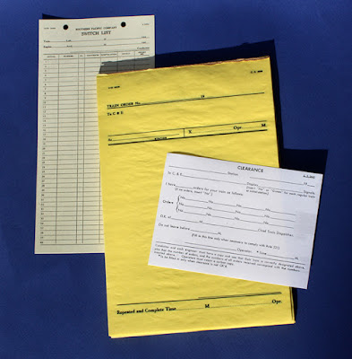
In addition to the above, I also use switch lists, “flimsy” train order forms, and clearance forms, all copied directly from SP originals, as shown below (at the time I model, SP did not put its name on train order or clearance forms). Prototype originals like this can be a starting point if your layout models a fictitious railroad. 

Last, I plead guilty to having contributed to the recent upsurge in interest and usage of prototypical waybills. Having over more than a decade, written 117 posts on the topic (for a guide to the first 100 of these, see this post: https://modelingthesp.blogspot.com/2022/11/waybills-part-100-guide.html ), along with several magazine articles, I can’t hide from it; but I do think this is an obvious feature to include on any layout that has switching. I won’t go further into waybills at this point.

The paperwork items described above are certainly typographic scenery, but more importantly, they are among the tools for prototype operation that follows the prototype. I will turn to that aspect, layout operation, in a future post.

Tony Thompson


Sunday, December 8, 2024

The 14th anniversary of this blog

My first post to this blog was on December 8, 2010, which makes today’s post a completion of 14 years of this activity. As of today, this is the 1730th post in this series, which seems a little unreal to me, but it must be true, because both Google and I keep track, and amazingly, I wrote them all. Whew! Certainly never expected all this back on this day in 2010. 

As I often do in the annual reflections, I have looked at the page view data provided by Google, the host for my blog. In the early years of the blog, it typically received 150,000 to 200,000 page views a year. More recently that has moved above 300,000 a year, and for this most recent year, it is at 385,000 page views. My total for the 14 years is now just a hair above 3 million page views. This is nothing compared to an internet “influencer,” but seems like a fair amount for a model railroading blog. 

The graph below is Google’s data for the past year (you can click on it to enlarge). I have no explanation for the areas of spikes in page views, but one can readily calculate that the daily average for most of these years is in the range of 500 to 1000 views a day. The two numbers at right are the page views (3.01 million) and the number of comments (2753). The drop at far right is because December isn’t complete.

Over the years, I have often received comments and questions in Google’s Blogspot process (that’s the 2.75 K number above), which appear at the bottom of each post, and that’s fine. I do respond to them. I have also frequently received questions or comments by separate email to me personally. Some of those have even generated entire posts in response, which shows that these communications can be quite substantive. They are part of what makes the blogging process interesting and fun for me.

One noteworthy event of the year was my completion of requirements for the Master Model Railroader award of the NMRA. I completed the last three achievement certificates last June, and have now been awarded the plaque as MMR  #772. I offered commentary on this, and showed the biography of me that was published in the NMRA Magazine in November, in a previous post (see it at: https://modelingthesp.blogspot.com/2024/10/personal-master-model-railroader-772.html ).

The plaque was delivered to me in a surprise move at an operating session at Steve Van Meter’s layout. Here is a photo of the operators on the layout that day, with the plaque being held by me and Earl Girbovan, to my left, who is now the Pacific Coast Region’s Achievement Program Manager (taking over from long-time stalwart in this job, Jack Burgess).

From far left, the folks in the photo are: Richard Brennan, Jim Radkey, John Wiley, John Sutkus, me, Bob Osborn, Earl, Mike Stewart, Andy Schnur, Steve, Bob Rosenbauer, and Jeff Allen. The person standing behind Andy and obscured by him is Seth Neumann.

Here is a better view of the plaque itself, alongside my John Allen award from PCR’s Coast Division, as it is placed in my layout room:

Meanwhile, operating sessions on my layout have continued. On the present version of the layout, that is, the one I’ve remodeled and completed here in Berkeley, the most recent pair of sessions (for comments about them, see: https://modelingthesp.blogspot.com/2024/11/my-latest-operating-session.html ),were the 95th and 96th sessions. I continue to feel, as do many layout owners, that the layout really comes to life and best expresses my ideas for it, when visitors operate it under my direction. I hadn’t thought this or expected it, years ago when I started work on a layout, but it’s true. And it definitely is satisfying.

The same remains true for the blog.It’s almost always fun to dream up topics, figure out what’s needed to describe and illustrate them, and then to compose a draft of each one. Sometimes the inspiration just flows, and a draft needs hardly any revision; more usually, a draft may need to be polished and refined numerous times to bring it to what I wanted to say. But it remains enjoyable.

Tony Thompson

Friday, December 6, 2024

Restoring an old Ulrich hopper car

I was recently browsing in my stash of old or unused freight cars, and came across an Ulrich metal hopper car from my teenage years. Among other things, it has Devore couplers in Devore draft gear boxes. The wire grab irons and lettering looked pretty good, so I decided to see what could be done with it — and to check whether it was a model of an actual prototype. Back in those days, there were relatively few commercial freight car models, and many were lettered for pretty much any popular railroad. 

(I have worked on a number of old Ulrich HO scale freight cars over the years, and have reported some of the projects in past blog posts. To find them, if you’re interested, use “Ulrich” as the search term in the search box at right. The Ulrich company, founded in the late 1940s by Charles J. Ulrich, was a mainstay of HO scale modeling the 1950s, and later became part of the Walthers line.)

Below is the model. Aside from the heavy sill steps, cast onto the white-metal car sides, it doesn’t look too bad. The model, unlike Ulrich hopper cars in later years, did not have cast-on grab irons at the right of each car side, but had free-standing Athearn metal ladders, not a bad idea under the “three-foot distance” rule. This is an immediate clue that this is an early Ulrich hopper.

Is this prototype? It sure is. Norfolk & Western built 12,500 cars like this in the 1930s, and the Ulrich model is a definite match. Below is a prototype photo (N&W photo), showing the first of these cars at Roanoke in 1936. You can just see the angled heap shields, just like the Ulrich model. Incidentally, anyone with even a faint interest in coal hoppers should own Bob Karig’s superb book, Coal Cars (University of Scranton Press, 2007), where I found this photo.

In 1953, the year I model, there were more than 8700 cars of these dimensions, though Class HL is not called out separately. That certainly means that an N&W hopper chosen at random might well be a car like this model.

Now I expect that at least some readers will be thinking, “What on earth is he thinking about, coal hoppers in California?” And in some ways, that’s true. But coal was certainly used in a number of ways in California at the time I model, as I discussed in an earlier blog post (see it at: https://modelingthesp.blogspot.com/2018/02/coal-in-california.html ). 

As mentioned in that post, little coal was ever found in California, and none of it very good, a natural result of California’s geologic history (marvelously explained for laymen in John McPhee’s excellent book, Assembling California, 1993). Accordingly, lots of it was imported, usually by rail, and sometimes from far away: thus an N&W hopper could be okay.

For those not familiar with the Ulrich models, they had cast white metal sides, ends, interior braces, and hopper gates, with sheet brass slope sheets. Thus it’s not surprising that the model weighs over 3 ounces, above the NMRA recommended weight for this car length. The model has metal sprung trucks, nice looking but with pre-RP 25 wheel flanges, so I will replace the entire truck.

The familiar Ulrich hopper kit of later years had a cast metal underframe, so that the assembly process would be as shown in the instruction sheet below (from the HOseeker website, https://hoseeker.net/Ulrich.html ). It is clear how the parts go together, and it makes a sturdy model. But this is not my model. (You can click to enlarge if you wish.)

My hopper, instead, happens to be the original Ulrich hopper, which had a pine center sill and balsa bolster/slope sheet supports. It also has applied ladders instead of the cast-on grab irons seen in the directions above. The directions for this somewhat different kit (sides and ends are like the later kits) is shown below (again, HOseeker). The wood parts are in the drawing at the top of the directions.

I will disassemble the underframe parts that support the draft gear, replace the balsa with styrene, and modify to accept a Kadee coupler box. I’ll describe that work in a future post.

Tony Thompson

Tuesday, December 3, 2024

Refining layout scenery, Part 2

In the previous part, I mentioned that no matter how carefully built the layout is, or how conscientiously maintained, careful examination will inevitably reveal a few layout areas that need work. Some time ago I began to be more systematic in this layout examination process, which I have termed “management by walking around” (see the post at: https://modelingthesp.blogspot.com/2018/07/management-by-walking-around.html ). And yes, I know this phrase is already a cliche in management circles.

My first venture back into this process, after some time off, was reported in the first post in the present series, describing an improvement in the location of my yard limit sign at Shumala. You can read that post here: https://modelingthesp.blogspot.com/2024/11/layout-scenery-refinements.html ).

One persistent problem on the layout has been in the area near the mainline tunnel, leaving Shumala westward. Near the tunnel mouth, there is a track gang’s tool house (at right below), a milepost (the telegraph pole with the white paint and the milepost number), a cable box (where telegraph lines from the pole go underground to traverse the tunnel), and a phone booth, all near a ground throw for the Shumala siding. This is a kind of tight location for throwing that switch, especially for those with fat fingers or diminished coordination.

The view above probably looks okay. But I realized long ago that some people would find the ground throw area a little confined, and would bump into the phone booth and cable box, so they aren’t glued down. As a result, after most operating sessions the area shown above looks like what you see below.

The real problem is that there isn’t room to put those two items farther from the ground throw, because the ballasted grade area narrows toward the telegraph pole. The obvious solution is to enlarge that grade down to and past the pole. My method was to mix up a little Sculptamold paper mache and adjust the contours appropriately, as you see here.

Next I painted the new area with acrylic tube paint, Burnt Siena, as a foundation for scenic materials to follow. I had originally planned to ballast the entire new contour, and put the phone booth and cable box back on top of it. But as I mentioned in the first post in this series, this is not what Southern Pacific usually did. They mostly put things like phone booths on the ground outside the ballast. I decided to do the same.

My usual base scenery material for “ground” is a medium tan earth, actually real soil collected around home plate on a softball diamond. I paint the area with dilute matte medium, apply the soil, and spritz it with “wet water,” water with a bit of detergent, this latter to help make sure all the scenic material is contacted by the matte medium. I then add a pinch of ground foam grass, so the ground isn’t perfectly bare. That gives the appearance shown below. Comparing the top photo in the present post, you can see how the level area has been enlarged.

Next I simply replaced the cable box and phone booth, but now much closer to the pole, leaving more space for “fat fingers” to operate the ground throw. These remain unglued for the reason stated above. I have considered adding a heavy cable from the top of the cable box up to the pole, representing the telegraph lines being brought down from the pole to an underground line, but have not decided how best to do this. So for the time being, this is the arrangement.

I have a couple more minor scenery refinements like these to describe, and will do so in future posts. To repeat, these are quite minor projects, chosen only to illustrate that even a fairly complete layout needs continuing attention to scenic details. Perhaps these posts will allow you to look at your own layout with a fresh eye.

Tony Thompson


Saturday, November 30, 2024

More about making crate and box loads

I have written about this topic before, and in the present post, am adding more examples, in part to show a different technique. Crated loads on flat cars and in gondolas are prototypical and relatively simple to make, and offer variety in what your open-top cars carry. I showed a variety of crate and box types in my first post on the topic, some years back (see it at: https://modelingthesp.blogspot.com/2012/03/open-car-loads-crates-and-machinery.html ). 

I expanded my ideas on this topic a bunch of years later, and treated it as a “Part 2” of the same topic, helpful in finding the predecessor, as it’s linked therein: https://modelingthesp.blogspot.com/2021/05/open-car-loads-crates-part-2.html . This post was about building some large crates as hollow styrene boxes, and the project completion was described later: https://modelingthesp.blogspot.com/2021/06/open-car-loads-crates-part-3.html .

The present post is about still another approach. I recently came across some hardwood offcuts from a project, and immediately thought of crates, but they were not square all around. On each one, the cut on one side was not square to one other pair of sides. But these could easily be braced to level them in use. I began by painting them light gray, then carefully examining them for any places that needed a little modeling putty, often lines of wood grain. I used Tamiya putty for this.

With the putty well dried and sanded smooth, another coat of paint made the boxes ready for use. Next came leveling them. Using a small square, as shown below, enabled me to identify exactly what size of stripwood or styrene to use as a level on each block.

Each wood block was different in what it needed. But the important part is that the styrene piece need not exactly fit at the extreme end, but could be placed  at an intermediate point, sufficing to level the block. An example is shown below.

With each block leveled in the way just described, I then added outside trim to hide the angle. For the block shown above, I used styrene HO scale 1 x 10-inch strip. The bottom of the block is shown below. When upright, of course, this is hidden.

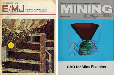
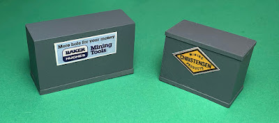
I then painted the trim to match the block. Next came a choice of label or emblem on the load. Many shippers added a prominent name or logo on shipments like these, and this makes the load interesting too. One can of course browse the internet for emblems of famous companies; this is what I once did in making an emblem for an appliance carton (see: https://modelingthesp.blogspot.com/2017/10/cardboard-cartons-part-2.html ), using General Electric. For the present project, I decided to use mining equipment, and where better to look than the ads in journals for that industry, like these:

Next came scanning of appropriate ads, reduction to a useful size for HO loads, and printing out on a high-resolution color printer at my local copy shop. Then the paper labels can be glued to crates or boxes with canopy glue.

It may be noted that the labels are added on the upper part of the crate. This is a deliberate choice so that they are visible when used as gondola loads as well as when they are flat car loads: see below. (You can click to enlarge.)

It might be asked, “Why mining loads? There’s no mine on that layout.” That’s true, but there was mining in the vicinity, as I’ve explored previously (see my post at: https://modelingthesp.blogspot.com/2016/10/modeling-mining-in-your-locale.html ). These crates can be destined to my off-layout mining company, Monarch Mining, which produces chromite ore. I have written a bit about this company and the ore (the post is here: https://modelingthesp.blogspot.com/2016/10/modeling-mining-part-2.html ).

With the completion of these loads, I have some additional crates to add to my freight car operations. Now to make some suitable waybills for the movement of these products . . .

Tony Thompson

Wednesday, November 27, 2024

Layout scenery refinements

This topic may seem a little surprising. The great majority of my layout has been pretty much complete for ten years, and parts of it are considerably older than that (for some previous posts about my layout’s history, see: https://modelingthesp.blogspot.com/2023/11/layout-origins-shumala.html or a more general one: https://modelingthesp.blogspot.com/2014/02/my-layout-description.html ). But problems do arise, or in some cases, persist for years. I plan to write several posts about correcting a few of them.

One of the areas on the layout that needs improvement is the location for my yard limit sign, for trains returning to Shumala from the Santa Rosalia Branch. This was a “small project” a number of years ago, and identified for branch train crews the point where they should stop and request yard entry. In my post, I even showed the SP standard drawing for such signs. (See that post at: https://modelingthesp.blogspot.com/2015/08/small-mdodeling-project-yard-limit-sign.html ).

Below is shown the area that includes the yard limit sign, and as may be evident, it is quite close to the track, close enough that steam locomotives with longer wheelbases often brush against it. This view is taken from right above the tunnel portal through which the Santa Rosalia Branch track exits the Shumala junction.

As you can see above, the problem is that the sign is already at the outer edge of the railroad fill as it is, and there isn’t room to put it farther from the track. So what is obviously needed is to widen that fill in the area near the sign location. 

This is pretty easy to fix. I simply mixed up a little Sculptamold paper mache and adjusted the contours appropriately, as you see below, to widen this area of fill.

Of course this snow-white look is not too appropriate for the California coast, so I painted it with acrylic tube paint, Burnt Umber, as a foundation for scenic materials to follow. One thought for the next step was simply to ballast the entire new contour. But this is not what Southern Pacific usually did. Photos of SP right-of-way almost always show things like signs located on the ground outside the ballasted area. I decided to do the same.

My usual base scenery material for “ground” is a medium tan dirt, actually very fine real soil collected around home plate on a softball diamond. I paint the area with dilute matte medium, apply the soil, and spritz it with “wet water,” water with a bit of detergent. A few pinches of ground foam grass then help the area blend with it surroundings. At the bottom of this view is the yard entry signal for Shumala (which I described in a previous post: https://modelingthesp.blogspot.com/2019/04/a-yard-entry-signal.html ).

The next step once all the scenic modifications are dry and solid, is to re-install the yard limit sign, which I did with canopy glue. This is the final result, looking to a casual observer as being much like it was before, but as you can readily see by comparing to the first photo is this post, now it’s really well clear of the track. In fact, the post is now 11 scale feet from the track center line, in conformance with the usual railroad standard that everything is clear within 8 feet of the track center.

I continue to tour the layout from time to time, with note pad or clipboard in hand, and try and find every area that needs to be repaired, upgraded, or even scenicked for the first time (I described this approach in a post some time back: https://modelingthesp.blogspot.com/2018/07/management-by-walking-around.html ). I will mention a few other recent refinements like this in future posts.

Tony Thompson


Sunday, November 24, 2024

Realistic layout operation

My topic today is realistic operation of a layout, including small layouts, and how to achieve it. A goal of many layout owners, including me, is to offer a realistic operating session when guest operators visit. But what do we mean by “realistic?” That’s what I want to go into.

I won’t spend too much time describing what actual layout owners have done or are doing, but intend to indicate what I think is required. This is drawn in part from experience hosting about 100 operating sessions on my own layout, but is also based on my experience on dozens of other layouts, many of them that I have operated on multiple times.

So what’s the core idea? For me, the core of realistic operation is following the prototype. Okay, what does that mean? I divide it into three parts: the first is in some ways the most obvious to observe, and yet the least important of the three, and I’ll explain why. This first point is realistic appearance. (I’ll return to the other two.)

There is an enormous amount of published material on this topic, and rightly so, because it has so many dimensions: scenery, trackwork, structures, rolling stock and locomotives, backdrops, on and on. And certainly this can matter, because just the first glimpse of  a visually great layout is usually stunning. But I think it’s important to recognize two points: first, that a visually stunning layout may not actually be very prototypical (Malcolm Furlow’s dioramas come to mind), and second, that there have been and still are any number of freelanced (not prototype railroads) layouts that meet the realistic appearance standard.

But before continuing, I should mention that I realize my topic is awfully close to the title of Tony Koester’s Kalmbach soft-cover book (2nd edition, 2013), which I reviewed when it had recently come out (you can see that post at: https://modelingthesp.blogspot.com/2014/03/tony-koesters-recent-operations-book.html ). I hope to go beyond the basics of Tony’s fine book.

As I stated above, the first thing that comes to mind in trying to define “realistic appearance” is fidelity to the prototype. How broadly can we define this? I once visited a layout built by an owner who wanted to imagine a future time when hydrogen fuel would be used in locomotives (and in the rest of the economy), and had rolling stock, locomotives, and industries thoroughly “imagineered” to suit this vision. But I think there is a real barrier to “realism” in such an approach, just as there would be in a layout with brightly-colored rolling stock on a layout (named for the owner’s children) called the “Jimmy and Susie Railroad.”

But that shouldn’t be interpreted to mean that free-lance layouts have a problem, provided their appearance and operation are in fact “realistic.” There are famous examples, like Allen McClelland’s Virginian & Ohio, Bill Darnaby’s Maumee, Jim Providenza’s Santa Cruz Northern, Tony Koester’s former Allegheny Midland, and Jack Ozanich’s Atlantic Great Eastern, all beautifully executed layouts with strongly prototypical looks and operation. Below is a photo I took on the AGE. I think it speaks for itself.

Still, choosing a prototype railroad to model can furnish a strong connection to a visitor’s existing knowledge. This was, in part, the inspiration for my own present layout. During the year I lived in England, attending model railroad exhibitions on many weekends, I saw the strength of the idea behind many portable exhibition layouts: an imaginary branch line of a familiar railroad. Then the locomotives, depots, freight car appearance, signals, and so on, are all familiar sights, making many features of the model obviously prototypical.

With that inspiration, I chose to model a long-time favorite, the Southern Pacific, while also choosing to follow the imaginary branch line idea. That in turn means that I model a real railroad in a fictitious place. For me, however, it’s more important that the scenes modeled and the operations practices should reflect the prototype’s practices, than that places are accurately modeled.

A single example of this is my two-car ice deck, a common size in small towns, with its features and details taken from PFE prototype practice (as I described recently at: https://modelingthesp.blogspot.com/2024/06/background-for-my-layout-ice-deck.html ). Below is a photo of it in use.

And to repeat, lots of authors have discussed this same topic. A notable example, rarely recognized these days, is Frank Ellison, in a number of his articles and publications. Particularly rarely recognized is his article from the January 1956 issue of Model Railroader, entitled “Fitness of Things,” focusing on any number of physical features of outstanding layouts. You can click to enlarge it if you’d like to read this page.

Of course, the real way to represent a prototype railroad in full is to buckle down to the challenge of choosing scenes to model, artistically compressing them to retain the core of their appearance, and then getting it all built. Probably there exists no better example than Jack Burgess’s Yosemite Valley, a superbly conceived and beautifully modeled and detailed double-deck railroad (photo by Venita Lake).

But beyond realistic appearance, I believe, come two further points, which both relate to the way in which the layout is operated. This post has already gotten long, so I will defer comments on these operation aspects to future posts, and will address the two parts of following the prototype not covered here.

Tony Thompson
Thursday, November 21, 2024

More on tank car placards

I have written a number of posts about the hazard placards used on tank cars, concentrating on my modeling era (1953). Placards were used to identify cargoes that were dangerous, and also to indicate dangerous empty cars. A summary of prototype practice was an early post of mine on this topic (see it at: https://modelingthesp.blogspot.com/2012/03/tank-car-placards-prototype.html ). 

Recently Michael Litant gave me two prototype placards. Both have tack or staple holes in them, indicating that they had been used on tank cars. Most tank cars had wood-faced placard boards, so this method of attachment is natural, but Union Tank (UTLX) cars had a metal frame into which a workman could slide a placard without tacks or staples. That usage then spread to other tank car owners from the 1930s onward. I’ve blogged about that too (see this example: https://modelingthesp.blogspot.com/2013/10/model-tank-car-placards-refinement.html ).

Here is one of Michael’s placards. This type of placard became standard in 1930, and was intended to be used to warn of any corrosive cargo, whether acidic or basic or otherwise capable of causing corrosion. As with most placards, this one was issued by a railroad (in this case, the Nickel Plate, as can be seen at the top of the placard; you can click on the image to enlarge it if you wish.) It was the railroad’s Form 841 and is dated 11-33, consistent with the introduction date mentioned above.

An earlier placard, with a date blank at right center indicating its introduction in the 1920s, is this one for flammable cargo (or as was then synonymous, “inflammable,” a possible source of confusion later eliminated by standardizing on the word “flammable”). This was Nickel Plate Form 761, and like the placard above, is 10.75 inches on a side.

It seems to me an obvious point that our model tank cars should carry these placards, depending on their cargo, or an “empty” placard if moving as an empty car. The most important category of “empty” cars is those containing small amounts of dangerous liquid or, sometimes even more dangerous, the vapor of the prior cargo. (Gasoline is an excellent example; a car full of vapor is much more explosive than a car of the liquid, having only a slight volume of vapor above the cargo.) Here is such a placard, helpfully showing its dimensions:

I have also posted several times about my methods for modeling and applying these various placards in HO scale (see for example, this one: http://modelingthesp.blogspot.com/2012/03/tank-car-placards-modeling.html ). I have made HO scale images of all the various placard types, and printed them out at my local copy shop, which has a high-resolution color printer. (Incidentally, 10.75 prototype inches converts to just a hair under 1/8-inch on a side for HO scale placards.)

Then in practice, I apply a loaded-car placard on one side of the model, and the empty placard on the other. That way, I can simply reverse the physical orientation of the model between sessions, to change its status from loaded to empty. In the examples below, the car belongs to Shell Chemical Co. In this first view, it is inbound to one of my industries, Pacific Chemical Repackaging, in Ballard, with a flammable placard.

In a future session (not necessarily the next one following),the car will be outbound as an empty, heading back to its owner. It’s shown below during switching at Shumala, being made ready for pickup by the mainline local.

I do think that model operations benefit from presence of placards, and was delighted that Mr. Litant gave me the two examples I’ve shown here. Thanks again, Michael.

Tony Thompson

Monday, November 18, 2024

My latest “Getting Real” column

Most readers know by now that I am one of a group of columnists who, in rotation, write the “Getting Real” column about prototype modeling in the on-line magazine, Model Railroad Hobbyist, or MRH. My most recent column has just appeared in the November issue. In recent years, MRH has been published in two parts: one that remains free to read on-line or download (visit www.mrhmag.com ) and in a second section, called “Running Extra,” which carries a fee, either for single issues or via subscription (cheaper per issue). The “Getting Real” columns have been appearing in “Running Extra.”

My new column is about modeling Southern Pacific flat cars. The idea to do that was stimulated by a question I was asked recently about the SP fleet of such cars, but also has a background in a talk I used to give some years ago, entitled “SP cars you can model,” emphasizing commercial models of the most common SP freight cars. Maybe that talk should be updated and revived. But that’s another story.

(For a full background on SP flat car history, my source is my book, Volume 3 in the series, Southern Pacific Freight Cars, Signature Press, 2004, covering automobile cars and flat cars.)

In the column, I began at the turn of the 20th century, with the first fully standard SP flat cars with steel underframes in any numbers, and the first to carry Harriman-standard class numbers, classes F-50-1, -2, and -3. The “F” stands for flat car, the “50” means 50-ton nominal capacity, and the last number is the individual class. Since those earliest cars were mostly gone from the fleet by the year I model, 1953, I have not modeled one.

But following those cars, SP adopted a flat car design that would be followed, with only minor changes, for over 20 more years and a dozen more flat car classes. This design originated in the Harriman era and thus is rightly called a “Harriman flat car.” Below is a good photo of one of the later classes in service at San Diego, Class F-50-8 car SP 38892, photographed by Chet McCoid on September 26, 1954 (Bob’s Photo collection).

The important things to notice about this car are the straight side sill, the blocking between the stake pockets which supports the wide deck reaching out to the outer edge of the stake pockets (called an “overhanging deck”), and the fishbelly center sill. All these features are well captured by the Owl Mountain Models kit for these cars (see my review of this nice kit at: https://modelingthesp.blogspot.com/2017/09/building-owl-mountain-flat-car.html ).

After World War II, SP turned to American Car & Foundry, and adopted their flat car design for several car orders. I went into some detail about these in the column. The most important cars were the 53-ft., 6-in. long ones, classes F-70-6 and -7, the latter a class of 2050 cars. Both classes are well represented by the Red Caboose HO scale model (dies now owned by the SP Historical & Technical Society, or SPH&TS, who have done a few re-runs of this model). 

Among the most characteristic loads carried by these flat cars in the 1950s was lumber, as part of a nationwide building boom. Shown below on my layout is a Red Caboose Class F-70-7 car with an Owl Mountain Models lumber load (for more on my building of this load kit, see: https://modelingthesp.blogspot.com/2014/08/open-car-loads-lumber-from-owl-mountain.html ).

I also described a few details about modifications to these flat cars by SP. An important modification was the addition of bulkheads for plasterboard service. In 1949, SP began adding low bulkheads to some of its new flat cars, and the SPH&TS has offered a really nice kit to duplicate these bulkheads (see my review at: https://modelingthesp.blogspot.com/2012/07/modeling-sps-bulkhead-flat-cars.html ). Here is a Red Caboose flat car with these bulkheads, being moved by a Baldwin road-switcher on my layout.

Loads in the earliest days were usually tarped rather than wrapped, but by 1953, wrapped loads were appearing. Here is my bulkhead flat car with a load made by Jim Elliott. Incidentally, loading plasterboard to the height of these bulkheads did amount to a nominally 70-ton load, the capacity of the cars, so there was a reason for the low bulkheads.

In 1953 and later, SP also converted dozens of Class F-70-7 flat cars for introduction of piggyback service, which began in June 1953. I showed prototype photos and some models, comparable to a recent post in this blog, which is at: https://modelingthesp.blogspot.com/2024/10/sp-piggyback-part-4-progress-on-3d.html .

Finally, I briefly covered some of the SP heavy-duty flat cars, the F-125 depressed-center cars and the F-200 four-truck cars. As those have been covered in some detail in my blog posts, I won’t go into them here. If you’re interested, the following posts can be consulted, along with the MRH article:

F-125: https://modelingthesp.blogspot.com/2024/05/an-sp-class-f-125-1-flat-car-part-2.html

F-200: https://modelingthesp.blogspot.com/2020/05/sp-200-ton-flat-cars-part-5.html

It was interesting to review prototype information and modeling resources to write a summary about SP flat cars of the early 1950s. I hope it was of some interest or value to MRH readers.

Tony Thompson

Friday, November 15, 2024

Model operations with SP cabooses: Conclusion

In this series of posts, I am describing the variety and assignments of cabooses for my layout operating sessions, which are set in 1953. I began with some Southern Pacific caboose history, and showed my model of a “temporary caboose,” a box car conversion, in Part 1 (see it at: https://modelingthesp.blogspot.com/2024/09/model-operations-with-sp-cabooses.html ).

The following post, Part 2 in the series, described the very widely used wood-sheathed cupola cabooses, around 620 cars of Class C-30-1, and an additional 80 or so cars of following classes C-40-2 and -3, built through 1930. The overwhelming numbers of these cars throughout the SP system made them a common sight in the era I model. That post is here: https://modelingthesp.blogspot.com/2024/10/model-operation-with-sp-cabooses-part-2.html .

For additional comments about SP cabooses in the area I model, it may be of interest to look at one part of my long interview with Malcolm “Mac” Gaddis, who first worked at San Luis Obispo as an electrician in September 1951 and remained there through 1954. I posted several parts of the interview; the part with comments about cabooses is here: http://modelingthesp.blogspot.com/2011/05/san-luis-obispo-operations.html .

Thee were two classes of steel cupola cabooses, both built at Los Angeles General Shops. In 1937, 50 cars of Class C-40-1 were built, followed in 1940 by 135 cars of Class C-40-3 (along with 30 cars of that class for T&NO). The most visible difference between the two classes was the hand brake, which was a vertical-staff design on C-40-1, and a geared hand brake on C-40-3. The photo below, taken at Eugene, Oregon in July 1954 (George Sisk photo, Charles Winters collection) has the handbrake visible.

The steel cupola cabooses were also still important in my layout’s era. I almost always assign them to mainline freights. Here’s an example, a freight on the passing track at Shumala, with SP 1026 at the end. The brass model Class C-30-1 caboose is from Precision Scale. Visible here is the primary spotting feature of this class, the vertical-staff handbrake (you can click on the image to enlarge it).

Below I show a mainline train passing the engine terminal at my layout town of Shumala, with a steel cupola caboose of Class C-40-3, SP 1129, on the rear. It’s also a brass model from Precision Scale.

After World War II, SP ceased building its own cabooses in company shops, and turned to commercial builders for additional cars. They also adopted a new caboose design with bay windows instead of a cupola. And of particular note, a new paint scheme was adopted: ends of the cars were painted vermilion, likely a test. I should emphasize that is is not the Daylight Orange applied to caboose ends from 1956 onward.

Below is a photo provided by Joe Strapac, showing two of these cars at Dunsmuir in the lower yard in March, 1953, with a familiar mountain looming in the distance. For more on these cars, those interested can consult my Volume 2 of the series, Southern Pacific Freight Cars (Signature Press, 2002), which is about cabooses.

In model form, these classes have been done by Precision Scale, and I have one of them with correct end color. It is always found on a manifest train in my layout operating sessions. Here SP 1253 brings up the rear of a train entering Tunnel 12, as it departs from Shumala on my layout. It’s a 1947-built Class C-30-4 car.

To wrap up this series of posts about how I use SP cabooses in my layout operating sessions, it should be evident that there is a pattern at work, one I have derived from prototype information and photos. It is just one small part of the prototype atmosphere I try to create on my layout.

Tony Thompson