Saturday, July 11, 2020

My latest MRH column: crossbucks

My latest column in the series, “Getting Real,” has appeared in the July 2020 issue of Model Railroad Hobbyist, in the “Running Extra” segment of the magazine. (It is at: www.mrhmag.com .) It is about crossbucks at railroad crossings, and how I built some really sturdy brass ones for my layout. Once upon a time, I had installed some molded plastic ones, and they were soon broken off by careless elbows. My crossings have been crossbuck-less for some time, waiting for this brass modeling project.
     As an SP modeler, I began with that railroad’s standard drawing for dimensions and lettering of crossbucks or, as the Southern Pacific called them, “highway crossing signs.” I addressed the SP design in a prior post (see it here: https://modelingthesp.blogspot.com/2013/03/streets-roads-and-all-that-part-2.html ), including the Common Standard no. 1320 drawing and a photo of an SP crossbuck. Those same materials are included in the MRH column.
     [The C.S. 1320 drawing in the article is a 1970, update, by which time the signboards themselves had become aluminum plate. In 1953, when I model, these were all wood.]
     It  may be useful here to reproduce the original C.S. 13 drawing, as in fact I did in an earlier post after Gene Deimling was kind enough to send me a copy (see that post at this link: https://modelingthesp.blogspot.com/2013/04/streets-roads-and-all-that-part-3.html ). The lettering on the post was dropped in the 1920s.


To summarize, the drawing calls for 6-inch square posts and 5-foot long blades, or 6-foot blades “where required by law.” The blades are nominally 2 x 10-inch boards.
      What I described in the article was making a fixture to solder together posts of square brass tubing and brass strip for the blades (obviously intended to be real sturdy). These were then cleaned up, painted white, and lettered with a Microscale decal set. Shown below are an as-soldered model, and a completed one with paint and lettering.


Installing these on the layout was simple, just involving drilling a hole for the tubing and inserting with canopy glue.
     Here is one of the crossings now protected with crossbucks like these, Chamisal Road in my layout town of Shumala. The depot is at left, and the bridge over the road carries the Santa Rosalia Branch away from its Southern Pacific mainline junction at Shumala. Note on the near crossbuck that there is an added sign, warning of “3 tracks.” (You can click on the image to enlarge it if you wish.)


The dark edge n the foreground of this photo is the layout fascia, so this crossbuck is very near the layout edge. That is why I decided to build these crossbucks out of brass.
     The above photo also shows the painted road markings at the crossing, another topic discussed at moderate length in the article, both as to existing highway standards and actual practices (in my case, in California). I showed how I applied these markings to my layout roads.
     In the MRH article, I only described the application of crossbucks and road markings to three of the railroad crossings on my layout. But in fact the layout has several more, and I will address each of those additional crossings in future posts.
     This has been an interesting project, and the crossbucks I built have already proved to be tougher than a grazing forearm! Whether they can hold up to a full operating crew, I guess is something I will find out one of these days. But they certainly improve the look of my road crossings.
Tony Thompson

Wednesday, July 8, 2020

Waybills, Part 72: is it merely visual?

I encountered a skeptic at a meeting, after one of my talks about creating and using model waybills in layout operations. His comment to me was, “Who really cares what waybills look like?” I was tactful at the time, and just replied along the lines that we all model in different ways.
     But the discussions I posted recently on the topic of waybill design, the three preceding posts in my long series about waybills prior to this one, brought out a similar comment, delivered by email. Those posts are about a larger-format waybill design, 5 x 7 inches (The second of three posts is at this link: https://modelingthesp.blogspot.com/2020/06/waybills-part-70-other-waybill-forms.html .)
     I would hasten to repeat that I accept differences in modeling goals and choices. But this particular comment sort of annoyed me, so I decided to try to make my point with a kind of whimsical illustration. What follows, I hope, will be recognized as just that, and nothing more.
     Let me choose such an illustration. Let’s say, that instead of waybills, we talk about box cars in model railroading. After all, such a model just fills a spot in a train, or on a siding. If it carries out that assignment, would we care what it looks like? Why not something like this? The body is a little simple, but it has trucks and couplers, so it will operate just fine.


Ah, you say, but that couldn’t serve as a model freight car; it isn’t lettered. Good point, and I can fix that pretty easily with a Post-It note; now it’s AB&C 1245.


Notice how convenient this is; whenever we need some different freight car for operation, just apply a different Post-It note.
     So is this an exaggeration? Of course, and intentionally so, but in my opinion not much more so than using a waybill along the lines of this one:


This “waybill” bears about as much resemblance to the prototype as does the wood-block box car I showed above.
     Do any of us use the prototype waybill in model railroading? Not to my knowledge, but the post I referenced in the second paragraph of the present post shows an effort to get close to the look and content of a prototype waybill. One might then have such a bill filled out like this:


I leave it as an exercise for the viewer, whether this waybill is more prototypical than the one shown just above it.
     What’s my point here? We may or may not aspire to reproducing all aspects of prototype railroading in our models and in our layouts. As many people have said, there is nothing wrong with any of the many versions of our hobby that an individual may choose to pursue. But if you ignore too many aspects of reality, and yes, I include paperwork in that, you run the risk that, as Tony Koester put it, you are just playing with interesting models of railroad hardware, not trying to model the reality of railroading.
     It has always been my modeling goal to try and reproduce at least a decent version of what railroading was like in my chosen locale and era, and on my chosen railroad. I want the crews that come for operating sessions to experience the flavor of what operating on the Southern Pacific was like in 1953. For  me, improving waybills are every bit as much a part of my goals as improving the looks of my locomotives and freight cars, or building better structures and scenery.
Tony Thompson

Sunday, July 5, 2020

Another impressive load

My recent work on models of heavy-duty flat cars, starting with the Army (USAX) car and continuing with the Southern Pacific 200-ton model from Funaro & Camerlengo, has led me to work toward making loads suitable for these cars. As an example, here is a link to my most recent post on that topic: https://modelingthesp.blogspot.com/2020/06/blocking-big-loads-part-2.html . Those previously described loads were from Multiscale Digital LLC.
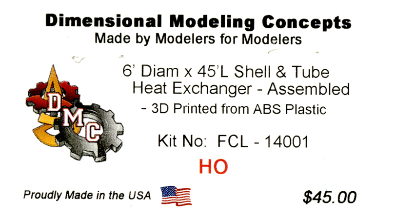
     Another relatively new company making loads that I’ve learned about is Dimensional Modeling Concepts, with a fairly extensive catalog. It mostly comprises 3-D printed piece or components. I especially like their large shell-and-tube heat exchanger, so I ordered one. You can visit their site at: https://dmcrrproducts.com . This assembly is 45 scale feet long, so would require at least a 50-foot flat car. To ensure that anyone interested knows the exact description, the box label is below.


I purchased the assembled model, but it is also available as a kit (the kit is $28).
     This load can be carried on a 70-ton flat car. Here’s a photo of the load itself:


To give an idea of the size of this model, the dimensions of the load are a little over six actual inches long and almost two inches high.
     On the DMC website is a photo of an example loading, shown on a modern flat car with extensive cable tie-downs. In earlier eras, most loads were less thoroughly restrained. Note also that this example of the heat exchanger is painted a browner color than the one you see above.


     For my own modeling of 1953, I blocked the load differently. The two “feet” received blocking, as they and only they are the support for this equipment when installed. To forestall fore-and-aft motion as well as tipping, I made hold-down rods from four of the tabs on the heat-exchanger body (instead of the six per side, 12 in all, in the photo above),
     For the blocking, I used scale 8 x 8-inch stripwood, with bolt heads indicated. For the hold-down rods, I used 0.025-inch iron wire that I had on hand. This wire has the advantage that it is iron-colored and so requires no painting, though I added some dabs of rust. The rods pass down through stake pockets on the flat car, and would have been threaded on the end, so that they could pass through a plate underneath the stake pocket and be secured with a nut. (You can click on the image to enlarge it, if you wish.)


The 70-ton flat car that you see here is a Red Caboose model, SP 140501, Class F-70-7. 
     I need to devise a suitable banner to identify the manufacturer, because that kind of signage was very common on eye-catchiing prototype loads like this. And of course there should be “DO NOT HUMP” signs at all four corners. But for now, I have a dramatic load to run in my through trains, even if there are no suitable recipients to which I could deliver this piece of equipment on my branch line.
Tony Thompson


Thursday, July 2, 2020

Waybills, Part 71: milling in transit

My introductory post on this topic laid out the prototype basis for this transit privilege (cost reduction), and gave some example waybill content, along with identifying a broad range of the commodities which might be subject to transit privileges (see it at: https://modelingthesp.blogspot.com/2016/05/waybills-part-50-in-transit.html ). The following post provided details and explained in particular how Southern Pacific instructed its agents to interpret, document and bill these kinds of shipments (that post is here: https://modelingthesp.blogspot.com/2016/08/wayblls-part-51-more-on-prototype-in.html ).
     As a brief summary, in-transit privileges meant that two short trips of a cargo, for example a load of grain that moved to a storage location for later delivery, then moved to destination, suffered from the markedly higher freight rates for shorter trips. The in-transit privilege allowed the entire trip length to set the freight rate. Some of the many ramifications and details of the in-transit rules are laid out in the two blog posts just cited.
     With that background on the complexities of the prototype milling-in-transit waybill process, I worked through the aspects of the paperwork that might be included in model railroad waybills (you can review that post at: https://modelingthesp.blogspot.com/2016/09/waybills-part-52-in-transit-bills-model.html ). My final product was a milling-in-transit waybill in the 2.5 x 3.5-inch size I use on my layout.


This bill really only is altered in the part at the very bottom, which is the in-transit documentation. The remainder of this bill is the regular freight waybill (as is true of the prototype Transit Freight waybill).  But when I tried filling out this bill, as noted in the post cited just above, there was very little room to do so. I accordingly looked forward to seeing what could be done in the 5 x 7-inch format being explored for Paul Weiss’s layout (see my prior description at: https://modelingthesp.blogspot.com/2020/06/waybills-part-69-another-approach.html ). .
     My first step was to make a larger version of the material at the bottom of the bill shown above, mostly just allowing more width per space, with the same four “minimalist” categories in columns, as you see below. The prototype transit waybill is AAR Form AD-134 (which can be seen in Railway Accounting Rules, Accounting Division, AAR, and in my “Waybills Part 52” post, linked in the third paragraph of the present post). It has 9 columns and three lines, compared to my 4 columns and two lines.


     With this addition, and a “transit” header, here is an example of a 5 x 7 version of a Transit Freight bill, in this instance for Nickel Plate. (You can click on the image to enlarge it if you wish.)


     I won’t go into how such a waybill is filled out, because I’ve already shown that in some detail in the three prior posts about milling-in-transit privileges (Waybill series Parts 50, 51, and 52 (links to all three posts are provided in the first three paragraphs of the present post).
     I don’t anticipate that too many model loads will use this waybill, particularly because it requires additional filling out, yet adds nothing to actual layout operating information. In that sense, using this bill, even more so than the standard freight waybill, is furnishing “typographical scenery,” as Al Kalmbach called it. The degree of play value achieved is something every modeler would have to decide for themselves.
Tony Thompson

Monday, June 29, 2020

My tank swap article in RMC

Back in 2011, an article of mine was published in Railroad Model Craftsman (July issue), aabout a project I did that swapped the tanks and underframes of two different manufacturers of model tank cars. These two models were an InterMountain 8000-gallon tank car, and an Athearn “chemical” insulated tank car, the latter tank cut down in size. I have mentioned this article before, but didn’t try to make anything available more than a summary. Here’s the link: http://modelingthesp.blogspot.com/2011/06/tank-car-modeling.html .
     More recently, I have had inquiries about this article, because the new owners of Railroad Model Craftsman magazine (RMC) are not making back issues as far back as 2011 available, so that my article is now essentially lost unless you happen to have that particular issue. To remedy the situation, I have uploaded a PDF of the original article, as I wrote it and submitted it (not as RMC printed it), to Google Drive. It is a layout with photos inserted close to the relevant text. You can access it at the following link, and either read it on line, or download:

https://drive.google.com/file/d/1MEl6D26XG3jJ8UqfLsXzVSQ8erE66Ly9/view?usp=sharing

     The article ended up creating a particular 8000-gallon car with a GATC-type underframe, a car leased to El Dorado Oil Works of Berkeley, California (edible oils, not petroleum products), and an insulated Warren Petroleum car on an AC&F underframe. Following are photos of the final product in each case. First, the El Dorado car, lettered with custom decals, and shown on my layout:


The prototype for the model is the following photo, a Wilbur C. Whitaker photograph taken at West Oakland, California in 1939, of this same car number.


     The other model tank car suffered from not having an exactly correct decal set (an old Champ set), but enough to make the most of what was done. The tank was cut down in length to fit the InterMountain underframe, and a new dome created. This photo also is on my layout.


     This article describes an interesting exercise, not because either of the tank car models produced are necessarily of wide interest, but in showing the techniques used. Those techniques may have far wider application beyond these specific projects.
Tony Thompson

Saturday, June 27, 2020

An Athearn metal SP tank car

Over the years, I have written several times in this blog about Athearn tank cars. One important reason is that the old “Blue Box” plastic models, both the single-dome and the three-dome, have been very widely used in the hobby. The size of these tank cars, about 12,500 gallons, is pretty large for the steam and transition era, but as has been widely noted, Athearn almost certainly was following a Southern Pacific prototype. The SP tank car fleet in the transition era was dominated by 12,500-gallon cars.
     That plastic Athearn single-dome car can in fact be converted into a fairly solid representation of the SP prototype. The basics of converting an Athearn tank car to SP prototype were described in my article from the SP Historical & Technical Society magazine, Trainline, issue 71, and  that original article was updated and refined in a previous blog post; it is at: http://modelingthesp.blogspot.com/2011/05/modeling-sp-tank-cars.html.
     Also of interest is the predecessor Athearn tank car models, all metal and very nicely done. I described both the early Athearn line, and the Globe Models tank cars that were acquired by Athearn in 1951, in one post (see it at: https://modelingthesp.blogspot.com/2017/10/some-old-metal-tank-car-kits.html ). To briefly summarize, in their own line, Athearn offered a 10,000-gallon car they called a “Shorty,” and two 12,500-gallon cars, a single dome and a three-dome.
     I restored one of the “Shorty” cars to service some time back, and enjoyed its excellent prototype lettering. I only had to upgrade to modern trucks and couplers (a project description is here: https://modelingthesp.blogspot.com/2013/07/returning-athearn-metal-tank-car-to.html ). I have not written, however, about the Athearn metal single-dome car of 12,500 gallons capacity, and that is the subject of the present post.
     One scheme Athearn has repeatedly produced over the years is the yellow “gasoline service” tank car of the Southern Pacific. One of my upgrade projects for the plastic Athearn tank car was to make that model more accurate, primarily increasing dome height, as I showed in a post (it’s here: https://modelingthesp.blogspot.com/2014/04/modeling-sp-gasoline-tank-car.html ).
     (History and extensive photography of SP tank cars, including the yellow gasoline scheme, can be found in my book on the subject, Volume 5 of the series Southern Pacific Freight Cars, subtitled “Hoppers, Covered Hoppers and Tank Cars,” Signature Press, 2008.)
     But this yellow scheme was also offered in Athearn’s metal tank car line. A few years ago I spotted one of these models at a swap meet, and immediately bought it. You can see what good shape it is in.


     The model has obviously been carefully handled and stored over the years, and it’s pristine. But it does have a couple of problems. First is that the modeler who built it put the body onto the frame backwards. The safety valves on the dome should be a the “B” end of the car (at left in the photo above).
     The simplest remedy would be to unscrew the frame from the body, rotate 180 degrees, and re-attach. But this would likely wreck the ladder attachments, which are peened over into the running board. What would work is to move the handbrake to the other end of the car (and re-locate the brake gear). In that process, it would be desirable to replace the somewhat crude brake wheel. That’s what I decided to do, in combination with ignoring the underbody brake gear; it isn’t too visible.
     A second problem is that the model has a dome walkway on both sides, whereas the SP cars only had dome walks on the left side. This is more difficult to correct without some surgery. Also, dome grab irons are missing. And finally, the SP cars had bottom sheets as well as the upper body in the same Colonial Yellow color, but the model has black bottom sheets. I decided to leave the problems along that required surgery or paint matching, and fix one problem that is easy to fix: the lack of any end lettering whatsoever.
     End lettering was pretty easy to fix. The decal set that I designed, originally for Gerry Glow and currently available from Tichy (set #10052), is intended for transition-era SP tank cars and is available in either white or black lettering. Obviously this car calls for the black. Here is the end with its new lettering. All of this, including gallonage and SP class number, are from my Tichy set.


Also visible here is the oversize and unrealistic brake wheel (which will be removed), and the metal two-rung sill steps at the ends. Also evident are the nice stanchions for the handrail. This model compares favorably in details with many newer models.
     I dug out a horizontal style brake wheel from my parts collection, added a phosphor-bronze wire staff, drilled a hole the same size in the opposite end sill from the one shown above, and cemented the staff in place. A little touch-up with black paint, and presto! we have reversed the location of the B end! while also adding a much better looking handbrake. Of course the brake gear underneath is now wrong, but it is closely attached to the center sill and not very visible, certainly far less visible than the handbrake staff.


Here you see again the nice two-rung sill steps, and of course the safety valves on the dome are now toward the correct, B end of the car, as intended.
     Despite the shortcomings described above, I will be pleased to include this car in mainline trains on my layout. In that service, not even SP freight car experts would likely spot the inaccuracies, and I will have the pleasure of operating a true classic, at least 60 years old and possibly closer to 70 years old. In model railroad terms, that can be called “ancient,” and I’m glad to have it in service.
Tony Thompson

Wednesday, June 24, 2020

Electrical wars, Part 17: staging

I have written a number of posts on the topic of finding and fixing electrical problems on my layout, as you can perceive from the series number of the title. (To readily find any of the previous posts in the series, use “electrical wars” as the search term in the search box at right. ) These posts do not represent any particular sequence or linked events, but describe separate electrical challenges I have dealt with.
     (I guess this series of posts is about “wars” because electrical problems make me feel like I am about to confront a challenging task. Luckily it’s not always that bad in the event.)
     This latest challenge arose in my layout staging, which is a 12-track transfer table. It has generally been pretty dependable since I built it, about ten years ago, based on a design by John R. Signor  (though some of the trackwork needed revision after some time operating with this staging, as I showed: https://modelingthesp.blogspot.com/2017/10/mind-gap.html ). Here is an overall view of the table, located beneath the town of Ballard on my layout.


This view shows the staging largely filled with freight cars, mostly consists of through trains, with only a few of them having locomotives. Since the photo was taken, this has evolved to where the majority of tracks contain complete, powered trains.
     When my staging tracks suddenly went dead recently, I started investigating what could be wrong. One problem I quickly discovered was that one of the staging tracks no longer had power at one end. Putting my trusty meter to work, I soon found the reason: a somewhat wide rail joint (foreground) had a broken solder connection, making it connect only intermittently. (That’s half an Atlas re-railer at left.)


This was quickly re-soldered and the track then functioned as it should. 
     But the larger problem recurred, essentially all tracks in the staging table going dead. It happened once, corrected itself, and then went very reproducibly dead. I then had to trace the path of power into the table and its distribution to the 12 tracks.
     Electrically, my control of the staging relies on a pair of 6-position rotary switches so that I can select any of the 12 tracks, with a switch between them to select which rotary is live. These controls were set up on a pretty simple panel (photo in this post: http://modelingthesp.blogspot.com/2011/02/staging-trackage-installation-4.html ). Shown below is the back of this panel, shown not because it is any kind of electrical marvel nor because of its incredibly neat workmanship, but only to illustrate the area in which I had to trace continuity,


The two rotary switches, at top, and the selector switch between them, are all evident. Below them is a pair of “on-off” switches, so that even when a track has been selected, it is not automatically powered unless I operate that switch.
     Power comes to this panel at the selector switch, then to the two “on-off” switches below, then to the rotaries. From the rotaries, the wires carrying power to each individual track head off to an array of terminal strips, as you see below, and thence to the tracks themselves, as are visible across the bottom of this photo. The view is looking up at the underside of the staging table.


The track numbers 1-12 are identified next to their part of the terminal strip and also by the feeders below them, through the plywood. The two multi-pin connectors visible (one of them end-on), bringing track power from the rotary switches, are so that the panel can be removed from the layout for work, without un-soldering or unscrewing anything.
     All this is documented in my “Layout Notebook” which contains many sketches of benchwork construction and of electrical arrangements, including identifying every wire by color and by its purpose in a particular area (I showed a page from this Notebook in an earlier post, which is at this link: http://modelingthesp.blogspot.com/2012/08/a-modeling-journal.html ).
     With this information in hand, I could start tracing the path of track power through all the complications shown above. I soon found a broken wire at one of the panel switches — how it was broken I don’t know — but readily re-soldered. Sure enough, the staging table then functioned perfectly.
     I tell this tale only to illustrate how one can trouble-shoot even complex wiring arrangements: if there is good access to that wiring, and if it is all documented so that you know what you are looking at, even ten years after you assembled all of it. That was this case for this problem.
Tony Thompson