Wednesday, May 1, 2019

A follow-up operating session

A month or so ago, I hosted three operating sessions on my layout for the San Francisco Bay Area operating weekend, BayRails VIII (I described some of the aspects of those sessions in a previous post, which can be found at: https://modelingthesp.blogspot.com/2019/03/my-sessions-at-bayrails-this-year.html ).
     I had introduced a number of new details in my sessions for BayRails, and naturally discovered also some problems, and wanted to follow up with session changes to reflect lessons learned. The perfect occasion was a visit by New Zealander Paul Hobbs and Canadian Greg Madsen, for whom I arranged a session on April 29. I added a preliminary session on April 28.
     As I had hoped they would, the sessions ran smoothly with the BayRails additions. One of my Frog Juicers had a loose wire, causing intermittent problems, but of course readily fixed — after the session. Otherwise, what I had designed for the operating patterns worked.
     Shown below are Paul (at left) and Greg, working in this photo at Ballard on my layout. At this point, Greg was the conductor and was managing the waybills for the local switching, while Paul was engineer.


     The two local operators who filled out the crew of four were Jim Radkey and Chuck Hakkarinen, whom you see below at Shumala. At this point, Jim (at left) was the conductor and Chuck was acting as engineer, as they organized the switching work before the arrival of the Guadalupe Local to exchange blocks of cars to and from the branch.


     This was the 48th session on the current version of this layout, and overall it went well. The corrections I made to the operating patterns after BayRails worked as I wanted them to, and most important of all, the visiting operators had a good time. That’s what it’s all about, for my money.
Tony Thompson

Sunday, April 28, 2019

Another PFE Class R-30-16, Part 2

This post continues a description of building a Terry Wegmann / Red Caboose kit for PFE’s Class R-30-16 rebuilt refrigerator cars. The previous post presented the early steps to construct one of these kits, with some particular goals in mind for the completed model (you can read it at: https://modelingthesp.blogspot.com/2019/04/building-another-pfe-class-r-30-16.html ).
     The R-30-16 class is very interesting historically, as the first of the PFE rebuild classes in which the superstructure was steel-framed, though retaining wood sheathing on the outside. It also was the first rebuilt class with a “solid steel roof” (the PFE term), which is the vital addition that Terry Wegmann created for this kit. And finally, with 3554 cars in the class, it is not only ne of the larger PFE rebuild classes, but a survivor too, with 3400 cars still in service in January 1953. Since I model 1953, it was essential for me to add another model of this class, as I mentioned in the prior post.
     In the previous post (link provided in the first paragraph of the present post), the car body had been assembled and painted Daylight Orange. I now built up all the details on the kit ends. One thing to choose here is what kind of handbrake would be used. On its rebuilds, PFE often used Equipco power handbrakes, though not always. Shown below is an E.R. Mohr photo of two PFE cars at Salinas, California in 1958 or 1959, with the nearer car being a member of Class R-30-16 and providing a good view of its Equipco hand brake. (You can click on this image to enlarge it if you wish.)


Note, incidentally, that after PFE ceased washing its cars in the early 1950s, that they became rather dirty in a few years. Show this photo to anyone who thinks your weathering is “overdone.”
     Modeling this handbrake well is easy today, because we have the superb Kadee rendition of this brake wheel in HO scale. Below is my kit end with details added, including the Kadee hand wheel.


     I also decided to letter the car body while it was still unassembled. This is a particular advantage for car ends, because the separate end can be laid down flat on the workbench (as you see it above), instead of having to stand the car model on its end to apply decals.
     I next turned my attention to the roof filler strips at the ends. The stock Wegmann roof leaves a gap at the top of the car end, which has to be filled. The kit contains a piece of 0.040 x 0.080-inch styrene strip. My previous experience is that the gap may not be exactly this size, as I mentioned in describing a previous R-30-16 build (you can see that description at: http://modelingthesp.blogspot.com/2011/08/small-modeling-project-pfe-r-30-16.html ). In that previous build, I filed the roof so that the 0.040 x 0.080 strip would fit at both ends. In the present build, I used the 0.040 x 0.080 strip at one end, and two pieces of 0.015 x 0.080 strip at the other — in other words, the gap at that end was actually 0.030 x 0.080 inches.
     With the body in its correct Daylight Orange color, it was time for decals. True to the comments I made recently about PFE lettering (you can read post at this link: https://modelingthesp.blogspot.com/2019/04/small-rant-manufacturer-lettering.html ), I used Microscale set 87-501 in the current version with Dick Harley’s excellent, recent artwork upgrading this set from older versions.


The 7-inch end lettering was applied, as it was still standard for wood-sheathed cars with wood ends in 1950.
     In the photo above, the fully lettered car is still on its interim truck support blocks but is otherwise ready to be weathered (I weather truck sideframes at the same time as the rest of the model). When first rebuilt, this class of cars largely retained their original T-section trucks, but as deadlines approached to remove these from service, more and more PFE cars got conventional AAR trucks. My model was equipped that way.
     All that really remains at this point is to weather the car, add some suitable chalk marks and route cards, and make a fresh paint patch where the reweigh data can be placed. Here is the result of those steps, pictured alongside the loading dock of the Guadalupe Fruit Company in my layout town of Ballard. (You can click on the image to enlarge it if you wish.)


     I now have two model PFE cars representing the 3554 cars of Class R-30-16. That’s a good start, but still falls short of my goal of having one model PFE car for every 1000 cars in the prototype PFE car fleet. Luckily I have one more of the Wegmann / Red Caboose car kits for this class, and one of these days, I will add that third -16 car to my fleet.
Tony Thompson

Thursday, April 25, 2019

A yard entry signal

My layout models a branch line of the Southern Pacific (a mythical one), and does not have a yard in the usual sense. But yard-like work has to be done at the branch’s junction with the Coast Route main line, despite the limited trackage, and accordingly the junction town, Shumala, is located in yard limits. On the main line, these limits extend beyond the modeled portion on the layout, but only extend a short way on the branch itself. There is a yard limit sign at that point, as I described in an earlier post (you can view it at: http://modelingthesp.blogspot.com/2015/08/small-mdodeling-project-yard-limit-sign.html ).
     On the prototype, yard limit rules permit any train or engine to enter the protected yard, operating at restricted speed and prepared to stop short of obstacles. (Rule 93 for yard limits was quoted in the post cited just above.)  But in some circumstances, including limited visibility into the yard, a number of railroads provided a signal indication at or  near yard limits, to inform train crews as to whether the entry track was clear. I decided to do the same.
     Since dwarf signals are often used in yard situations, I decided to use that type of signal. And since my layout models Southern Pacific, I wanted to use an SP-style signal. For an example of how Southern Pacific dwarf signals looked, one can consult the ample prototype photography that exists. Shown below is a detail of a Robert Hale photo at Lathrop, California, taken during the transfer of the through chair car from the Sacramento Daylight to the San Joaquin Daylight in 1955. (The power on No. 52 happens to be SP 4449.) The dwarf signal is located between the tracks.


(The Hale photo is from the M.D. McCarter collection.)
     My dwarf signal is intended to control entry to yard limits when arriving from the branch. I decided that the right location would be alongside the yard limit sign. I made up a level pad on the hillside slope below the tunnel that leads to the branch, as you can see at the lower center of the photo below. The yard limit sign is across the tracks from the pad.


     Digging around in my catalogs of detail parts, I found a perfectly appropriate model, a Century Foundry kit for a Union Switch and Signal dwarf. Here are front and back views of the kit package, showing how the signal is intended to look when assembled. The sketch of the assembled kit, right, looks just like the SP prototype shown in the photo at the top of this post.


This kit originally contained clear plastic rod, intended as a light pipe so that the signal could be illuminated. But in my layout situation, the signal is aimed into the tunnel, so that approaching train crews could see it. That in turn means that model railroad operators cannot see it. I will need to provide a signal repeater panel for operators.
     This signal kit is still available, in the Century line now owned by Showcase Miniatures. They have revised the kit so that LED lighting can be installed right in the signal body, instead of with a light pipe, and it is now identified as kit no. 2194. You can see it on their website if you’re interested (the relevant page is at: https://www.showcaseminiatures.net/ho_scale/ho_scale_signals_wigwags_trackside_details/ ). This is the package label.


     The Century Foundry kit is simple, with just four parts. I cleaned them up with a small file, and assembled them with CA. I then painted the signal, and its junction box, with silver paint, to suggest the usual SP practice of aluminum paint on such appliances. I added an Alexander battery vault cover, their part no. 3110. Below is shown the installation. Because it needs to be aimed into a curved tunnel, it is some ways from the track, instead of right alongside, as it would be for tangent track.


     To portray the signal more in layout context, I took a photo looking down the track toward the yard, with the yard limit sign on the right. This is about the view that could be obtained standing on the hillside next to the tunnel.


     As I mentioned, now that the signal is installed, I need to make a repeater panel for the layout fascia, so that arriving train crews have a signal indication without craning their necks to try and see the signal itself. That repeater installation will be described in a future post.
Tony Thompson

Monday, April 22, 2019

Panel-side hopper car, Part 2

In the previous post, I described some of the background to the rebuilding of United States Railroad Administration (USRA) hopper cars on the New York Central system. I always liked the look of hoppers rebuilt with the pressed-out side panels, and although my layout only has occasion to host hopper cars from time to time, I wanted to have such a model. That first post is at this link: https://modelingthesp.blogspot.com/2019/04/a-panel-side-hopper-car.html .
     In that prior post, I showed the painted but unlettered Tichy panel-side hopper car that I had acquired. I now had a small dilemma. The largest group of NYC System cars converted with panel sides was the P&LE set of 1419 cars (described in the previous post), thus the likeliest to be seen off-line. But partly because there is a good Tichy decal set for the NYC cars, I leaned toward making my car an NYC car. After all, NYC had several groups of these cars, one of them comprising 250 or so cars.
     I went ahead and ordered Tichy decal set no. 10282. Its lettering is an excellent match to the 1933 appearance of the NYC panel-side car shown in the previous post. So before checking the history (no doubt you can see where this is going), I jumped in and decaled one side of my panel-side hopper.


This looks nice and I was enjoying how well it was turning out. Then, unfortunately (in one sense), I decided to check some background while waiting for the decals to be totally dry so I could do the other side of the model. I soon discovered some problems.
     By 1940, these cars were being renumbered into the 832100–832599 series, and before the end of World War II, there were no more cars remaining in the 416000-series numbers. Not only that, but the distinctive, spaced-out initials and car numbers in the scheme shown on the model above had been superseded by a more conventional NYC lettering arrangement.
     Obviously this means that the decals I had applied represented a scheme that was long gone by my 1953 modeling date. But being neither a NYC fan as such, nor much of a hopper car enthusiast, I considered whether I could simply ordain a modest time warp for these cars, so they could retain their 1930s car numbers and paint scheme. Reluctantly, I decided not to add to the many existing compromises already present on my layout by having a completely unhistorical paint scheme and number on this car.
     Instead, I considered whether I should go with the P&LE option. For my 1953 era, P&LE is a better choice anyway; not only did the cars keep their as-rebuilt car numbers in the 37000–38418 range, but 1389 of them were still in service in 1953. By contrast, NYC was scrapping many of its USRA hoppers by 1953, including the panel-side ones. I hunted through my decal stash and came up with Champ set HN-19 for P&LE reporting marks.
     The Tichy decal set could then be used for various capacity data and for its much superior car numerals. It also has a nice NYC emblem, though its lot number is wrong. But I used it. Here’s why. The Tichy decal lot number is 387-H, the correct lot for the cars when they were original USRA hoppers, but lot numbers in the 600s were applied when the panel side rebuilds were done. In cases like this, I adhere to one of Richard Hendrickson’s principles: the important thing is that some kind of lettering is visible above the NYC emblem. Few if any modelers will try to read lettering this small on a passing model.
     Now I went ahead and painted out the reporting marks and car number that you see above, and replaced that lettering with the P&LE material from the Champ HN-19 set.


     The fact that this is a hopper car, and would have experienced heavy use, means that it needs to be weathered fairly heavily. I will confess I stop my weathering short of making reporting marks and numbers impossible to read, since my models are used in operating sessions where their identity needs to be discoverable. But some cars do need to be fairly dirty. I have added paint patches for the reweigh and repacking lettering.


The removable coal load above is a homemade balsa block covered with real coal of “lump” coal size. Modelers often seem unaware that coal was shipped in several sizes, at least four fairly different sizes. Industrial, steam and metallurgical coal were all normally shipped as lump. But take a glance at the photo below, taken at Williamson, West Vierginia on the N&W in 1941 (Library of Congress). ’Nuf said.


Anyone wanting to know much more about hopper cars, and for that matter about coal sizes and coal shipping, may wish to look into the late Bob Karig’s excellent 420-page book, Coal Cars (University of Scranton Press, Scranton, PA, 2007). The photo above is the frontispiece of the book.
     My P&LE hopper car model is now ready to enter service on the layout, and will usually be carrying metallurgical coal, not only from the Pittsburgh Region but from other areas where met coal is mined and a P&LE hopper car might be confiscated for loading. I discussed in a blog post awhile back, the historical fact that eastern and midwestern met coal did come out to the West Coast in some circumstances, including strikes (see that post at: https://modelingthesp.blogspot.com/2016/06/coal-traffic-on-my-layout.html ), and obviously this P&LE hopper can represent part of such an event.
Tony Thompson

Friday, April 19, 2019

Waybills, Part 63: filling out

In previous posts, I have explored many aspects of what waybills are and how they are used, always with the goal of informing model operations. Many of these prior posts can be found by using the word "Waybills" as a search term in the search box at the right. If you have particular interests within this topic, add one or more appropriate words to the search term you use.
     The present post goes back to a very basic point, and one about which I am often asked: how does a model waybill get filled out? It was stimulated in particular by a recent layout visitor, who shall remain nameless, and who phrased it this way: “How do you dream up these waybills?” Overcoming  a faint instinct of outrage at the word “dream,” I realized he really meant to ask, “where does the information come from?” That’s certainly a legitimate question.
     The first issue to recognize is that of how cars are chosen for loading. Modelers often imagine all on-line loading to be in home-road cars. If this had been done on the prototype, obviously half of all car miles would have been empty car-miles, since all arriving foreign cars would be unloaded and sent home empty, while home-road cars were loaded exclusively. It was to reduce this problem that Car Service Rule 1 was written to say, in essence: “Do not load a home-line car if suitable foreign car is available or can reasonably be obtained.”
     (For a full quotation of all six of the primary Car Service Rules, along with the necessary map of destination zones, you may wish to read my post at: https://modelingthesp.blogspot.com/2011/09/waybills-12.html . But do we need to try and follow these Rules? In the decade after World War II, AAR data showed that around 70 percent of all carloadings did follow the Rules, so it seems to me that we should strive to do the same.)
     Thus, if you model, say, Seattle and are envisioning a load arriving from somewhere in Ohio, you might think it would surely be carried in a local railroad’s car, the New York Central or Erie or perhaps the B&O. But in fact that yardmaster in Ohio would have Rule 1 in mind, and would prefer to put that Seattle-bound load into a car of a northwestern road, say Milwaukee, NP or GN, or even a railroad with nearby connections such as SP or UP.
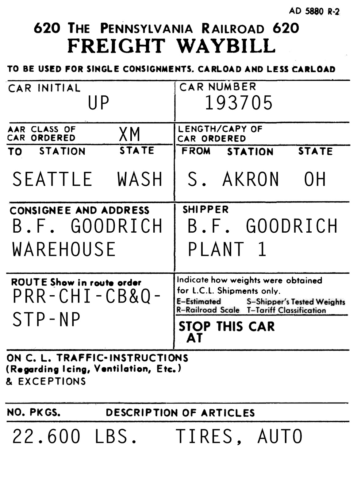
     So if you are choosing a load of Ohio origin, say automobile tires from Akron, how do you go  about it? First, you  need to know which railroads served Akron, so that you can choose a blank waybill for one of those railroads. I like to use the Kalmbach-reprinted 1928 “Railroad Atlas” that I described in a previous post (see it at: https://modelingthesp.blogspot.com/2012/05/waybills-24-routing.html ).
     In the Ohio map in that book, you will discover that Akron was served by the Erie, Pennsylvania, B&O, and of course the Akron, Canton and Youngstown. I have blank waybills for all four. But I like to check at this point about specific industries and whether there was a switching district. I do have the Pennsylvania Railroad “List of Stations and Sidings,” effectively a Shippers Guide, reprinted by Rails Unlimited (see their website at: http://railsunlimited.ribbonrail.com/Books/shippers.html ). That document shows that both B.F. Goodrich and Firestone each had two plants served by the PRR. So one option is a PRR waybill for that load of auto tires.
     As it happens, B.F. Goodrich maintained a warehouse in Seattle, served by the NP. That information comes from the Great Northern Shipper Guide, also from Rails Unlimited. So that’s a logical destination for a carload of auto tires. We could well use an AC&Y waybill for an  interesting look, but I think the PRR choice makes sense too.
     Next let’s imagine that you have a freight car needing work in your yard or in staging, such as the car shown below. This would be a good fit to the waybill we are designing, that is, to load the shipment of tires into this Union Pacific car. That is true, even though the routing will not take the car via UP (Car Service Rule 2), because the empty can readily be returned to UP in the Seattle area.


     Another interesting aspect is routing. This is potentially a very complex and sometimes arcane topic, but I simplify the problem by choosing a direct route via major railroad lines (which are indicated in the 1928 Atlas). Putting all this together, we might arrive at something like the following:


My blank waybills are Photoshop tiff files, and they are filled out using the Type tool in Photoshop.
     There are of course many options that go into a final result like the above waybill, as I have tried to indicate in describing the preparation process, but few of them are “wrong” and the modeler can, within limits, please his or her personal preferences. Obviously a great many railroad car ownerships could be chosen in place of the UP car in this bill, and other routings could be chosen. And as indicated, one of the other railroads serving Akron could be the source of the blank waybill.
     You may notice in particular that I used two Shipper Guides in this process. I have copies of these most helpful documents for 12 railroads, most of them obtained from Rails Unlimited. There are other sources of information about industries in different locations, but I find these the most convenient. The real point is seek out and use such information for waybill purposes. 
     This post describes a fairly typical example of the process by which I make up my waybills. The information sources are ones that are readily available to anyone who wishes to follow a similar process, and the guiding principles, such as Car Service Rules, are well documented. But I should emphasize that no “dreaming” need be involved.
Tony Thompson

Tuesday, April 16, 2019

Lumber loads: an additional gondola

I have mentioned several times in past blog posts that gondolas were often used for lumber loading along Southern Pacific lines. These were of course less convenient to load as well as to unload, but were pressed into service when there were not enough flat cars. Many prototype photographs testify to this practice, and I will include here one such photo, one I have shown before. The reason to repeat it will be evident in a moment. It is an SP company photo in southern Oregon (negative N1660-14), of a train headed to California with many loads of lumber.


Note in this photo that there are at least 7 gondolas carrying lumber. But of particular interest is the one nearest the camera, which is a Louisville & Nashville gondola. Naturally the reason(s) this car was in Oregon and could be confiscated for loading are lost to time, but cars like this were certainly free-running cars and could have been loaded anywhere, and then moved anywhere else.
     I decided I would model one of these cars, and use it for lumber loading, among other things. How much can we learn about this car from the photo above? Here is an enlargement of just the gondola (you can click on these images to enlarge them further, if you wish).


     The car number can’t be read in its entirety, but clearly the first two digits are 74. Note also the center panel of the car side, which has no diagonal brace. This is a well known spotting feature of the composite GS gondolas designed by the USRA (United States Railroad Administration) in connection with World War I.
     It’s thoroughly documented that L&N received 1000 cars of the USRA composite gondola, numbered 74000–74999, and these cars remained in service, still with wooden side sheathing, into the 1950s.They were accompanied by an additional 1000 cars that were USRA clones, the 73000 series, and as late as 1950, 1523 of these original 2000 cars were still in service.
     I had an InterMountain styrene model of the USRA gondola, so decided to letter it for L&N. (I don’t know if IM has ever offered this model in that lettering.) I had an old Champ set, no. HN-72, and used the lettering there for this car. The lettering obviously is simple, so this was a quick job. Once lettered, I weathered it fairly strongly, on the basis of how the car looks in the photos above, and in view of the car’s age.


     This car was chosen for modeling on account of the lumber load in it, in the photo at the top of the present post, so I decided to see how the recent Owl Mountain “narrow” lumber load would fit into it. (I reviewed this kit a few posts ago: https://modelingthesp.blogspot.com/2019/04/lumber-owl-mountains-recent-kit.html .) As I had hoped and expected, it fit fine, as shown below.


By the way, the prototype photo at top shows a load in this car which is considerably shorter than this Owl Mountain load, and I will return to shorter lumber loads in a future post.
     I now have an intriguing car to carry lumber to customers on my layout, a car owned by a railroad distant from my California setting, but one that vividly illustrates what it means for a car to be a “free runner,” as most gondolas were in fact.
Tony Thompson

Saturday, April 13, 2019

Small rant: manufacturer lettering

I confess to suffering from an advanced case of “type geek” disease, which manifests itself, among other ways, in noticing when lettering is the wrong shape or proportion. Of course it also snaps its head up when wrong fonts are used, but that’s a different rant. In the present post, I will address freight car lettering, specifically Pacific Fruit Express.
     As regular readers of this blog will know, this is not a new topic for me. Some time back, I posted an illustration of lettering on a Challenger brass model of a PFE Class R-40-26 car, emphasizing how wide of the mark — to state it tactfully — the lettering was, and I included a photo of the Challenger lettering (that post is at this link: http://modelingthesp.blogspot.com/2013/05/correcting-brass-model-of-pfe-car.html ).
     When I phoned my contact at Challenger, he admitted that the lettering has been turned over to the Korean producer, who had been directed to “match” a prototype photo. Obviously their understanding of “match” was not informed by any typographic knowledge. My solution to the problem was, as described in the post just cited, to repaint and entirely reletter that model.
     To show what we are aiming at, I show below a segment of a prototype photo of a PFE car’s initials and car number (it happens to be a steel car). The details of this Roman-style lettering were a Common Standard used by both UP and SP, and were constant with PFE for decades.


Allow me to call your attention to the proportions of the letters and the numerals, specifically the contrast of thick and thin strokes in the letters, and the somewhat condensed numerals. Sadly, manufacturers continue to ignore this kind of information.
     Today, thanks to the painstaking and meticulous work of Dick Harley, we have superbly accurate PFE decal lettering. I reviewed one of the sets with the new Harley artwork, the set for black-and-white Union Pacific emblems, Microscale set 87-501, at this link: https://modelingthesp.blogspot.com/2013/07/the-new-microscale-pfe-decal-set.html .
     Another set, the one for lettering with the red-white-blue Union Pacific emblem, Microscale set 87-414, has been similarly upgraded, and I used it in replacing some old Microscale car numbers, from a 414 set of the 1990s, to have more correct car numerals (I showed those lettering comparisons here: https://modelingthesp.blogspot.com/2016/05/replacing-bad-decals.html ).
     Subsequently, that project was extended to a number of the older PFE reefers in my fleet, to bring them all up to “snuff” (see those projects at: https://modelingthesp.blogspot.com/2016/05/that-bad-decal-project-part-2.html ).
     Despite Harley’s fine work on PFE lettering, manufacturers apparently continue to “wing it” for PFE lettering on models. Here is a recent Red Caboose (now part of InterMountain) lettering area, which you can compare to the lettering shown above.


The numerals are too short in comparison to their width, that is, they are not accurately condensed. The number “9” shows this clearly. And the serifs on the letters P, F and E do not match the prototype.
     For an additional comparison, I show below the PFE lettering from current Microscale set 501, and you can readily see that it agrees well with the prototype photo at the top of the page, while further showing the poor qualities of the Red Caboose lettering immediately above. Again, look at the numbers 9, 7 and 6 in these two photos.


The current purveyor of both its own steel-car models of PFE classes, and of the Red Caboose wood-body cars, InterMountain, does not do much better on its steel cars. Here again, comparing their lettering to either the prototype photo at the top of this post, or to the Microscale 501 lettering immediately above this paragraph, clearly shows the shortcomings of the letters, though numerals are much closer to prototype than the letters.


     I want to emphasize also that there should be no lack of sufficient information on this topic, including copious photographic coverage of PFE, both in the “PFE book,” as it is often called (Pacific Fruit Express, 2nd edition, Thompson, Church and Jones, Signature Press, 2000), and also in the Southern Pacific Historical & Technical Society book,  Southern Pacific Freight Car Painting and Lettering Guide (Harley and Thompson, SPH&TS, Upland, California, 2016), which contains an extensive section, nearly half the book, about PFE, with Harley’s excellent lettering research.
     Luckily, all the problems mentioned above are readily corrected with the outstanding recent Microscale sets I have mentioned in this post. But beware, if you have some elderly Microscale 414 or 501 sets stashed away. The old ones do not have the excellent Harley artwork, which is more recent. If you are thinking of doing some PFE lettering, don’t scrimp. Plunk down the price of the new 414 and 501 PFE decal sets, and find a new home for those old sets . . . perhaps in the round file.
Tony Thompson